You sized the stack correctly. You used the right discharge units, you picked the right frequency factor, you specified DN 110 where the calculation asked for DN 100, and the drawing still came back from the reviewer with three connections circled in red.
That is the normal experience of designing soil and waste pipework, and it happens because sizing and layout are two separate rulebooks. The calculation tells you how much pipe you need. It says nothing about where a branch is allowed to touch the stack, how far the lowest connection has to sit above the drain, or what happens to a trap seal when a riser steps sideways around a beam. Those rules live in different clauses, several of them in annexes, and a few of the most useful ones are printed only as dimensions on a figure.
This page collects them. Every dimension below is traced to BS EN 12056-2:2000 or to the UK’s Approved Document H, with the clause, table or figure number printed next to it so you can quote it in a drawing review.
Key takeaways
- A branch entering a stack creates a no-connection zone on the opposite wall. For branches over 65 mm it is 200 mm regardless of stack size; for smaller branches it varies with stack diameter — 90 mm on DN 75, 110 mm on DN 100, 210 mm on DN 125, 250 mm on DN 150 (EN 12056-2 Figure ND.5).
- The bend at the foot of the stack needs a minimum 200 mm centre-line radius, and the lowest branch must sit 450 mm, 750 mm or a full storey above the drain invert depending on building height.
- Offsets in the wet stack are worst when they are short — under 3 m produces large pressure fluctuations (clause NC.2.4). This reverses most people’s intuition.
- Two different trap seal numbers get conflated constantly: you design to a 50 mm seal, but the system must retain 25 mm under working conditions.
- EN 12056-2 and Approved Document H do not always agree, and the standard contradicts itself once — its own figure legend prints 740 mm where the clause text says 750 mm.
The layout rules that decide whether a drainage drawing passes review
There are three families of layout rule, and they fail in different ways. The first governs where pipes may meet: a branch discharging into a stack disturbs the air core, and another branch in the wrong place catches the discharge. The second governs the bottom of the stack, where falling water turns a corner and generates the highest pressures in the system. The third is not a geometry rule at all — it is the thing the first two exist to protect, which is the water sitting in every trap in the building.
Keep the boundary with sizing clear, because it saves you looking in the wrong document. Discharge unit summation, the frequency factor, the choice between the four EN 12056-2 system types and the branch gradient tables are all covered in our companion guide to soil stack sizing to EN 12056-2. Everything on this page assumes the sizing is already done and asks a different question: given these diameters, where is the pipework actually allowed to go?
One sizing rule does carry over, because it constrains layout directly. Clause 5.5 states that the nominal diameter of discharge pipes shall not be reduced in the direction of flow. Whatever you do with the geometry below, you cannot solve a clash by stepping the stack down a size below the last connection.
What a reviewer is actually checking
A drainage drawing review is not a hunt for creativity. It is a short list of dimensions, and the reviewer works down it in roughly this order: are any two connections too close together on the stack, is the lowest connection high enough above the drain, is the base bend generous enough, does the stack change direction anywhere it carries water, and does every appliance have a trap with the right seal depth reachable by an air path. Five checks. The rest of this page is those five checks in detail.
No-connection zones: where a branch may not join the stack
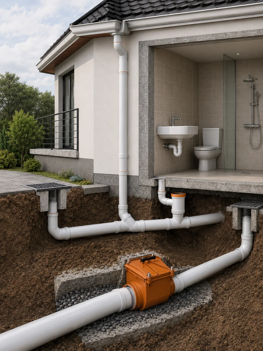
This is the rule that catches most drawings, and it is the one most commonly half-remembered. When a branch discharges into a stack, the flow crosses the bore and runs down the far wall. Anything connecting to that far wall immediately below the entry gets the discharge pushed into it. EN 12056-2 calls the result cross-flow, and the fix is a keep-out area on the opposite side of the stack.
Clause ND.3.3.3 states it directly: to prevent cross-flow from a large diameter branch connection such as a WC branch into a smaller diameter branch such as a bath branch, the smaller branch should be connected to the stack at or above the centre line level of the larger connection, or at right angles or less to it, or at least 200 mm below. Three legal positions, and the third is the one everybody quotes.
The zone table nobody publishes in full
Here is where the merchant guides get thin. Most of them print a single number — 200 mm — and leave it there. That figure is correct only for large branches. EN 12056-2’s Figure ND.5 carries a table, and the zone opposite a small branch depends on the stack diameter you are connecting to.
| Situation | Stack diameter | Height of no-connection zone | Source |
|---|---|---|---|
| Opposite a large branch (over 65 mm, e.g. a WC branch) | Any | 200 mm, independent of stack diameter | EN 12056-2 Fig. ND.5, legend 1 |
| Opposite a small branch | DN 75 | 90 mm | EN 12056-2 Fig. ND.5 b) |
| Opposite a small branch | DN 100 | 110 mm | EN 12056-2 Fig. ND.5 b) |
| Opposite a small branch | DN 125 | 210 mm | EN 12056-2 Fig. ND.5 b) |
| Opposite a small branch | DN 150 | 250 mm | EN 12056-2 Fig. ND.5 b) |
Read the DN 125 row again. The zone opposite a small branch on a DN 125 stack is 210 mm — larger than the 200 mm figure everyone remembers for WC branches. A designer who has internalised “200 mm is the worst case” will place a connection 200 mm below a small branch on a DN 125 stack, believe it is conservative, and be 10 mm inside a keep-out zone. Manufacturer literature will not catch it either: Polypipe’s technical guide publishes only the DN 110 and DN 160 rows, because those are the sizes it sells.
The boundary tolerance that saves a redesign
One sentence in clause ND.3.3.3 is worth memorising, because it converts a lot of near-misses into compliant drawings. No branch may be fitted such that its centre line falls inside a zone — but its centre line may be on the boundary of the zone. Exactly 200 mm below a WC branch is legal. At 199 mm it is not.
The practical consequence: when a connection lands marginally inside a zone, you are usually millimetres from compliance rather than facing a re-planned bathroom, and moving the boss down to sit precisely on the boundary is a legitimate resolution rather than a fudge. Note the measurement is taken from the centre line of the incoming branch, not from the socket face or the edge of the fitting — a distinction that quietly moves the answer by half a pipe diameter if you get it wrong.
When there is genuinely no room
Where several waste appliances have to connect close to a WC branch and the arithmetic simply does not work, the engineered answer is a waste manifold. EN 12056-2 clause ND.3.3.2 permits branch discharge pipes to connect to a manifold whose cross-sectional area equals or exceeds the pipework connecting into it, provided the manifold is designed to prevent cross-flow internally. Manufacturers build these specifically for the problem.
Brett Martin’s waste inlet manifold accepts up to four appliances close to the WC branch and discharges into the main stack below the 200 mm restricted area, and Polypipe’s MAN5 soil manifold does the same job. The manifold does not repeal the zone rule; it moves the point of entry to somewhere the rule is satisfied.
There is also a simpler dodge available when only one pipe is in the way. Because a right-angled connection is one of the three legal positions, a waste branch that would be illegal directly opposite a WC connection may be legal at 90 degrees to it at the same level. Brett Martin’s guide notes the same escape route in reverse — a 50 mm parallel branch connection can prevent the situation arising at all.
The base of the stack: bend radius and the lowest connection
The bottom of a stack is where the highest pressures in a drainage system occur, and where the cheapest fittings decision does the most damage. Water arriving at the base has to turn from vertical to horizontal. If it turns sharply, it forms a curtain across the bore, the air being dragged down the stack cannot get past, and the pressure spikes.
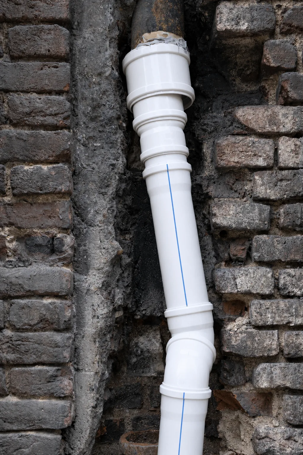
EN 12056-2 clause ND.3.5.2 requires bends at the base of a discharge stack to be of large radius — a minimum 200 mm centre-line radius — or to be formed from two 45-degree bends. Approved Document H paragraph 1.26 says the same thing in statutory language: the bend at the foot of the stack should have as large a radius as possible and at least 200 mm at the centre line. Where there is room, the standard’s Figure ND.6 asks for more, giving the preferred radius as twice the internal diameter.
The two-45s option is worth knowing about because it is often the only one that fits. A 200 mm centre-line radius long-sweep bend on a DN 110 stack is a physically large fitting, and in a ground-floor duct with a fixed slab level it may not go in. Two 45-degree bends achieve the same gentle turn in a shorter vertical drop and are explicitly permitted.
How high the lowest connection has to sit
The second rule at the base is a vertical exclusion. Because back pressure is worst just above the bend, the standard keeps branch connections away from it, and the distance scales with how much water can arrive from above.
| Building | Minimum from lowest branch to drain invert | Source |
|---|---|---|
| Single dwellings up to 3 storeys | 450 mm | AD H para 1.11; EN 12056-2 ND.3.5.3 |
| Multi-storey up to 5 storeys | 750 mm (see the discrepancy below) | AD H para A.5; EN 12056-2 ND.3.5.3 |
| Over 5 storeys | Ground floor appliances get their own stack, or discharge direct to drain or gully — effectively one storey height | AD H para A.6; EN 12056-2 ND.3.5.3 |
| Over 20 storeys | Ground and first floor appliances get their own stack | AD H para A.6 |
The 740 mm problem, and what to actually write
Here is a genuine inconsistency inside BS EN 12056-2:2000, and it is the kind of thing that turns into a fortnight of emails if you meet it for the first time in a review. Clause ND.3.5.3 says that for systems up to five storeys, the distance between the lowest branch connections and the invert of the drain should be at least 750 mm. The legend to Figure ND.6 — the figure the clause refers you to — gives the same dimension as L greater than or equal to 740 mm.
Design to 750 mm. Approved Document H paragraph A.5 says 750 mm, Polypipe and Brett Martin both publish 750 mm, and clause text carries more weight in an argument than a figure legend. But know that the 740 mm exists, because sooner or later a contractor will produce the figure and ask why your drawing is 10 mm more conservative than the standard he is holding, and “the clause and the figure disagree, so we designed to the stricter of the two” is a complete answer that takes ten seconds.
Note also what the over-5-storey rule really costs. It is not a dimension you can squeeze — it removes the ground floor from the main stack entirely. On a six-storey residential block that means a second stack or a direct drain connection for every ground-floor appliance, which is a builder’s-work and a drainage-layout decision, not a fittings decision. It has to be made at the layout stage, and it is the single most expensive thing on this page to discover late.
Offsets in the wet stack, and why the short ones are dangerous
An offset is a sideways step in the stack. The structural engineer puts a beam where your riser wants to go, the architect moves a wall between floors, and the stack has to dodge. Everyone knows offsets are undesirable. Almost nobody knows which ones are worst.
EN 12056-2 clause NC.2.4 gives the counter-intuitive answer: offsets of less than 3 m length in the wet part of a stack can produce large pressure fluctuations. A short, sharp dogleg is the dangerous case. The intuition that a small step is a small problem is backwards, because the shorter the offset, the more abruptly the falling water is forced across the bore and the more completely it blocks the air path. The same clause notes that changes in stack direction also cause detergent foaming, which brings its own pressure effects.
What the rules require when you cannot avoid one
Clause ND.3.5.4 sets the position plainly: offsets in the wet portion of a discharge stack should be avoided, and where they have to be fitted, large radius bends should be used. In a secondary ventilated stack system, connections to the discharge stack should be made above and below the offset — you ventilate around the problem.
Approved Document H paragraph 1.27 adds a UK dimension the EN text does not give: in a building of not more than 3 storeys there should be no branch connection within 750 mm of the offset, and in a building over 3 storeys a ventilating stack may be needed with connections above and below the offset. Same principle, an explicit number attached.
There is one free case. Clause ND.3.5.4 states that offsets above the topmost appliance or branch connection do not require venting. Above the highest connection the stack is a dry vent, not a wet stack — nothing is falling through it, so there is no air core to disturb. If the roof geometry forces a dogleg and you can put it above every connection, it costs you nothing.
Two related constraints belong here because they are decided at the same moment on the same drawing. Approved Document H paragraph 1.27 also requires that in buildings over 3 storeys, discharge stacks are located inside the building — Brett Martin’s guide states the same as a flat prohibition on external stacks above three storeys. And clause NC.2.7 warns that wind blowing across roofs produces pressure fluctuations near parapets and building corners, so a stack terminated in one of those positions can develop unacceptable pressure fluctuations in the system below. Where the stack ends is a layout decision with consequences all the way down.
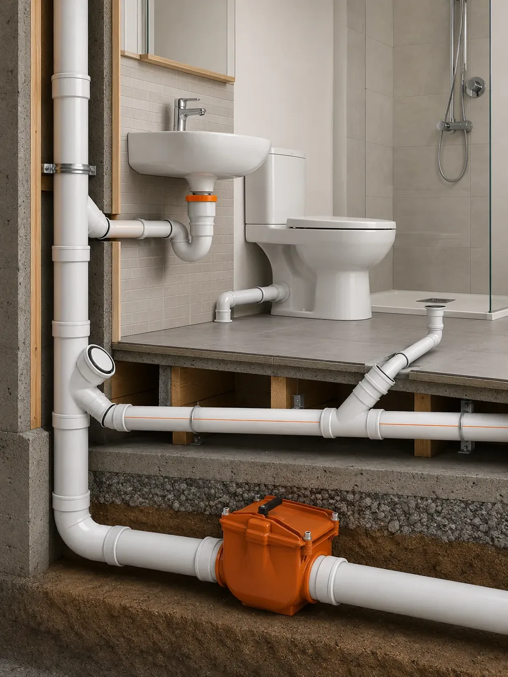
Trap seal protection: the 50 mm you design and the 25 mm you keep
Everything above exists to protect a small volume of water sitting in a U-bend. It is worth being precise about which number applies when, because two different figures are in circulation and people mix them constantly.
You design to 50 mm. EN 12056-2 clause 5.4 is unambiguous: the depth of water seal shall be not less than 50 mm. Approved Document H Table 1 sets the same 50 mm seal for WC pans, with deeper 75 mm seals for appliances such as sinks, and allows a reduction to 38 mm only where an appliance discharges directly to a gully.
The system must retain 25 mm. Approved Document H paragraph 1.3 requires that under working and test conditions traps retain a minimum seal of 25 mm of water or equivalent. That is the number a commissioning engineer measures. A layout that starts with a compliant 50 mm seal and loses more than half of it in service has failed, even though every trap on the schedule was specified correctly.
Three mechanisms, three different culprits
EN 12056-2’s informative annex NC sets out how the seal is actually lost, and the distinctions matter because each mechanism points at a different part of the layout.
Self-siphonage (clause NC.2.1) happens to the trap of the appliance that is discharging, when its own branch discharge pipe runs full bore. The moving column of water pulls the seal out behind it. The standard’s Figure NC.1 adds a detail worth knowing: after the initial loss, air passing through the trap causes further water loss by a pumping action.
Clause NC.2.1 lists what makes it worse — funnel-shaped appliances, the length, gradient and diameter of the pipe, the trap and waste fitting design and the free cross-sectional area at the outlet, the presence of an overflow connected into the trap, the design of bends, and whether the branch is vented at all. This is the mechanism that punishes long unvented branches, which is why full-bore System III branch design and self-siphonage are so closely linked.
When someone else’s discharge is the culprit
Induced siphonage (clauses NC.2.1 and NC.2.2) empties a trap belonging to an appliance nobody is using. It happens when a shared branch runs full bore, or when flow in the vertical stack creates negative pressure. Clause NC.2.2 locates it precisely: suction occurs below discharging branch connections and below offsets. This is the diagnostic signature everyone recognises — someone runs a bath upstairs and a basin two floors down gurgles and loses its seal.
Back pressure (clause NC.2.2) is the opposite sign and comes from the opposite end. Positive pressures occur above offsets and above bends in stacks, blowing foul air through the trap water seal and sometimes causing seal loss outright.
The CIBSE Journal CPD module on foul water drainage in high-rise buildings gives the physical cause: a positive pressure at the base of the stack is caused by the entrained airflow being impeded by a water curtain formed where the water downflow separates from the pipe wall, and it may compromise or even blow out the trap on branches close to the base. That is the direct link back to the bend radius rule — the sharp base bend is not an abstract compliance item, it is the thing that produces the water curtain.
Reading the symptom back to the drawing
| Symptom | Mechanism | Where to look on the layout |
|---|---|---|
| The appliance in use empties its own trap; a gurgle at the end of the discharge | Self-siphonage (NC.2.1) | Branch length, gradient and diameter; whether it needs a branch vent |
| An unused appliance loses its seal when another one discharges | Induced siphonage (NC.2.1, NC.2.2) | Shared branches; connections below a discharging branch entry; connections below an offset |
| Foul air pushed into the room; traps on low floors disturbed | Back pressure (NC.2.2) | Base bend radius; the height of the lowest connection; offsets above the affected floor |
| Whole-system disturbance during heavy rain or downstream blockage | Drain surcharge (NC.2.5) | Below-ground capacity; whether extra stack ventilation is needed at the base |
| Pressure fluctuations traced to the drain rather than the stack | Interceptor trap nearby (NC.2.6) | Presence of an interceptor close to the stack base; additional ventilation |
One caveat on scope. A trap can also empty through evaporation in an appliance nobody has used for weeks, or through capillary action along a strand of hair or fabric caught over the weir. Both are real, and neither is a layout defect — no dimension on a drawing prevents them. They belong to maintenance and appliance selection, and they are not mechanisms EN 12056-2 addresses in the clauses above. If a trap in an occupied, well-designed building is dry, look at the layout first; if a trap in a rarely used guest bathroom is dry, look at the calendar.
Fitting geometry: what to specify so the layout behaves
The rules above are dimensions on a drawing. They become real when someone orders fittings, and the wrong fitting quietly undoes a compliant layout.
Clause NC.2.3 explains why the shape of the entry matters at all. Suction is produced in the stack below a discharging branch inlet, and its magnitude depends on the radius or slope of that inlet. A large radius or a 45-degree entry tends to minimise the suction; a near-horizontal entry with a small radius does the opposite. The same discharge, through a different-shaped fitting, produces a different pressure regime — and it is the negative pressure below the entry that pulls seals out by induced siphonage.
The numbers are specific. Branch connections should be made in the direction of flow using swept entry branches with a minimum 25 mm root radius, and for DN 30 pipes serving wash basins the root radius should be greater than 25 mm. Approved Document H paragraph 1.17 gives the statutory version: junctions on branch pipes of about the same diameter should be made with a sweep of 25 mm radius or at 45 degrees, and connection of branch pipes of 75 mm diameter or more to a stack of equal diameter should be made with a sweep of 50 mm minimum radius or at 45 degrees.
Two details that get missed on the schedule
Where a small branch joins a much larger one, position matters as well as angle. Approved Document H paragraph 1.18 asks that branch pipes up to 40 mm diameter joining branch pipes of 100 mm or greater should, if practicable, connect to the upper part of the pipe wall of the larger branch. Come in at the top and the small pipe stays clear of the flow in the large one; come in at the side or the bottom and it is a drain for the larger pipe’s contents.
And if a branch needs its own vent, the vent has a position too. Approved Document H paragraph 1.22 requires branch ventilating pipes to be connected to the discharge pipe within 750 mm of the trap, at least 25 mm diameter — or at least 32 mm where the branch is longer than 15 m or has more than 5 bends.
Brett Martin’s guide flags a national variation on that figure: 300 mm maximum in Northern Ireland. If you are working to a UK-derived drawing outside England and Wales, that is exactly the sort of number to confirm rather than assume.
Venting a branch, and the valve alternative
Air admittance valves are the internal alternative to running every vent to open air, and they are covered in more detail alongside soil vent pipe termination rules and heights. One practical limit worth carrying: Brett Martin states that air admittance valves can be fitted to sanitary pipework in buildings up to ten storeys high, and must sit vertically above the flood level of the highest appliance served, in a non-habitable but accessible space. Treat the storey count as manufacturer guidance rather than statute — Approved Document H itself sets no storey limit, though paragraph 1.33 does require that valves are not used outside buildings or in dust-laden atmospheres and remain accessible for maintenance.
Specifying a PP or UPVC drainage package against these rules?
For specifiers and contractors putting a drainage stack on a drawing for a project outside their home market. Our PP drainage range is certified to EN 1451-1 and the published schedule lists single and double branches at 45 and 87 degrees from 50×50 to 200×200, elbows for stack offsets, siphons and ring-seal sockets at article-code level — so a fittings schedule can be matched to the geometry the standard requires.
Two things worth knowing before you ask: there is no published minimum order quantity for drainage fittings, because the order minimum is set per project against your own fittings schedule and size mix; and root radius, socket geometry and branch angle are all verifiable on a physical sample before you commit, which is the check we would recommend on any first order. Dimensional questions on a specific connection can go to the technical team by WhatsApp or email.
Same drawing, different rulebook: EN 12056-2 against Approved Document H
If you buy or specify across borders, the awkward case is not a project with no standard. It is a project where the drawing arrives in UK vocabulary and gets built somewhere the UK document has no force — a pattern common enough on export work that it is worth setting out where the two documents diverge.
They agree on more than they differ. The 200 mm base bend radius, the 450 mm low-rise clearance, the avoidance of wet-stack offsets, the 50 mm design seal and the ban on reducing diameter in the direction of flow are common ground. The divergences are narrow and specific.
| Item | BS EN 12056-2:2000 | Approved Document H (2015) |
|---|---|---|
| Lowest connection, up to 5 storeys | 750 mm in clause ND.3.5.3; 740 mm in the Fig. ND.6 legend | 750 mm (para A.5), no ambiguity |
| Stub stack limits | Fig. ND.6 a) shows 2.5 m and 1.5 m | 2 m branch centre line, 1.3 m WC floor level (para 1.30) |
| Branch exclusion around an offset | Vent above and below; no distance stated | No branch within 750 mm, up to 3 storeys (para 1.27) |
| Unvented branch limits | Tables 5 and 8, by system type and filling degree | Table 2: WC over 80 mm, max 8 connected, 15 m, gradient 18 to 90 mm/m |
| Gradient expression | Percentage | Millimetre fall per metre |
That last row causes more friction than its size suggests. Neither document uses the 1:40 and 1:80 ratio notation that UK site vocabulary defaults to, so a drawing annotated “1:80 to EN 12056-2” cites the standard for something the standard does not say. Write the gradient the way the document you are citing writes it.
The mechanism that governs all of this is national. EN 12056-2’s Annex A records national and local regulations and practice, and the accompanying national annexes carry each country’s own values — which is why the UK document exists at all, why Wales publishes its own Part H, why Scotland reads 2.5 m for a stub stack where England reads 2 m, and why Northern Ireland allows 300 mm rather than 750 mm for a branch vent connection.
For any project, the sequence is: design to EN 12056-2, then obtain the national annex or local regulation for the country the pipe will be installed in, and reconcile the differences before the fittings schedule is priced. Do not assume the EN values are the whole obligation; the standard itself points you to the national rules.
This is also where product standards enter. The layout standard governs geometry; the EN 1451 product standard for PP soil and waste pipework governs what the pipe and fittings themselves must be, and both have to be satisfied. Our PP drainage system range is built to EN 1451-1, which is what allows a fittings schedule to be read against a specifier’s drawing without a translation step. If you are still choosing between materials for the stack itself, the comparison of PP silent against UPVC soil pipe sets out which system suits which building.
Worked review: what we check when a riser drawing arrives
Take a single stack in a five-storey residential block. DN 110 throughout, one bathroom group per floor: a WC on a 110 mm branch, a bath on 40 mm, a basin on 32 mm, all entering the same stack on each floor. Ground floor appliances are on the stack too. Here is the review, in the order a checker runs it.
Check 1 — the branch entries on a typical floor
The WC branch is over 65 mm, so it creates a 200 mm no-connection zone on the opposite wall of the stack, independent of stack diameter. The bath and basin branches are small, and the stack is DN 100 in standard terms, so each of them creates a 110 mm zone opposite. If the bath enters directly opposite the WC and 150 mm below it, that connection is inside the WC’s 200 mm zone and fails. Three legal fixes: bring the bath in at or above the WC centre line, bring it in at right angles or less to the WC connection, or drop it to at least 200 mm below.
Check 2 — the small branches against each other
Assume the fix chosen is to drop the bath to 200 mm below the WC. Now the basin needs a home. Opposite the bath branch there is a 110 mm zone on this stack. Placing the basin 60 mm below the bath, opposite it, fails. Placing it 110 mm below, opposite, sits exactly on the boundary — legal, because a centre line may lie on the boundary. In a real riser, where floor-to-ceiling space is the constraint, that 110 mm is the difference between one arrangement and a re-planned bathroom.
Check 3 — the lowest connection
Five storeys puts this building in the 750 mm band: the lowest branch connection must be at least 750 mm above the invert of the tail of the bend at the foot of the stack. If the ground-floor WC branch sits 600 mm above the invert, it fails. It can be raised, or the ground floor appliances can be taken to their own stack or direct to the drain — which is what the standard would require anyway if a sixth storey were added.
Check 4 — the base bend
Specify a bend with at least a 200 mm centre-line radius, or two 45-degree bends. If the duct cannot take a long-sweep bend of that radius on DN 110, the two-45s arrangement is the compliant alternative, not a compromise. Where space allows, twice the internal diameter is the preferred radius.
Check 5 — direction changes
If the riser steps sideways at third-floor level to dodge a beam, that offset is in the wet portion. It needs large radius bends; on a building over 3 storeys, a ventilating stack with connections above and below the offset may be required, and the UK document keeps branch connections 750 mm clear of the offset in low-rise cases. If the same dogleg could be moved above the top-floor connections, it would need no venting at all.
Check 6 — what changed on the schedule
Two checks failed and both were fixed by geometry rather than by re-planning rooms. The consequences for procurement are small but specific: the bath and basin connections move to different boss positions on the floor-level branch fitting, the ground floor connection either rises or comes off the stack entirely, and the base fitting is confirmed as a long-radius bend or a pair of 45-degree bends. If the bathroom group had been tighter — say a second WC opposite the first — the answer would have been a waste manifold discharging below the restricted area rather than four separate bosses in 400 mm of stack.
Where this stops. A layout check against published dimensions is not a design check, and it is not a substitute for the responsible engineer’s own review or for the approval of the local authority. Where the drawing and the applicable national annex disagree, the annex governs and the drawing has to change — that is a decision for the designer of record.
The checklist, condensed
- No branch centre line inside a no-connection zone: 200 mm opposite large branches, 90/110/210/250 mm opposite small branches on DN 75/100/125/150.
- Lowest connection at least 450 mm, 750 mm, or one storey height above the drain invert, by building height.
- Base bend at least 200 mm centre-line radius, or two 45-degree bends.
- No offsets in the wet stack; if unavoidable, large radius bends plus venting above and below.
- Every appliance trapped at 50 mm minimum seal, with the layout capable of retaining 25 mm in service.
- Swept entries in the direction of flow, 25 mm root radius minimum, 50 mm for 75 mm branches and above.
- Diameter never reduced in the direction of flow.
Run those seven in order on any riser and you will catch the failures a reviewer catches, at the stage where they cost a redrawn detail rather than a rebuilt duct. Take the seven-point list to your next drainage drawing before the fittings schedule is priced, because every one of these failures is cheaper to fix on paper than in a duct.
Frequently Asked Questions
How close can a waste pipe connect to a WC connection on a soil stack?
Not directly opposite within 200 mm below it. EN 12056-2 clause ND.3.3.3 allows three positions: at or above the WC branch centre line, at right angles or less to it, or at least 200 mm below. A centre line exactly on the 200 mm boundary is acceptable.
Is the no-connection zone always 200 mm?
No. The 200 mm figure applies opposite branches over 65 mm and is independent of stack diameter. Opposite a small branch the zone follows the stack: 90 mm on DN 75, 110 mm on DN 100, 210 mm on DN 125 and 250 mm on DN 150, per Figure ND.5.
What is the minimum bend radius at the foot of a soil stack?
A minimum 200 mm centre-line radius, or two 45-degree bends instead. That is EN 12056-2 clause ND.3.5.2 and Approved Document H paragraph 1.26. Where space allows, the preferred radius is twice the internal diameter.
How far above the drain must the lowest branch connection be?
450 mm in single dwellings up to 3 storeys, 750 mm in multi-storey buildings up to 5 storeys. Above 5 storeys, ground floor appliances need their own stack or a direct drain connection; above 20 storeys the first floor joins them.
Why does EN 12056-2 show 740 mm in one place and 750 mm in another?
It is an inconsistency in the standard. Clause ND.3.5.3 says at least 750 mm; the legend to Figure ND.6 prints 740 mm for the same dimension. Design to 750 mm, which is what Approved Document H paragraph A.5 requires.
Are offsets allowed in a soil stack?
They should be avoided in the wet portion. Where unavoidable, use large radius bends and, in a secondary ventilated system, connect above and below the offset. Offsets above the topmost branch connection need no venting at all.
Why are short offsets worse than long ones?
Clause NC.2.4 records that offsets of less than 3 m length in the wet part of a stack can produce large pressure fluctuations. The shorter the step, the more abruptly falling water is thrown across the bore and blocks the air path.
What is the minimum trap seal depth?
50 mm as a design value under EN 12056-2 clause 5.4, with 75 mm required for some appliances in Approved Document H Table 1. Separately, the installed system must retain at least 25 mm of seal under working and test conditions.
Why does one appliance lose its trap seal when a different one is used?
That is induced siphonage. A shared branch running full bore, or negative pressure in the stack below a discharging branch entry or below an offset, pulls the seal from a trap on an appliance nobody is using.
Does EN 12056-2 or Approved Document H govern my project?
EN 12056-2 sets the European method, and Annex A directs you to national and local regulations. Approved Document H is the England and Wales route to compliance; Wales, Scotland and Northern Ireland each carry their own variations. Confirm the national annex for the country of installation.