A 40mm shower waste enters a 110mm stack. The fitting is the right size, the joint does not leak, the installer signed it off. Six weeks later the occupant reports a smell in the bathroom and a gulp from the basin every time the bath drains. Nothing has broken. The branch was simply run at a length and a fall that the connection was never permitted to hold, and the trap has been losing its seal since the day it was commissioned.
That failure is not a workmanship problem and it is not solved by a better boss adaptor. It is a specification problem, and the numbers that prevent it are published, short, and almost entirely absent from the pages that rank for this question. This article puts them in one place: how long a branch of each diameter may run, at what fall, where on the stack it may land, what entry geometry it needs, and how to tell which of three different physical mechanisms is emptying a trap that looks correctly installed.
Key takeaways
- Length and fall trade against each other. A washbasin branch (32mm trap per Table 1, 30mm minimum pipe per Table 2) may run 1.7m unventilated at a fall of 18–22mm per metre, but only 0.7m once the fall reaches 87mm per metre. Steeper is not safer (AD H Table 2).
- Upsizing is an alternative to venting. Take that same basin branch to 40mm and it runs 3.0m; at 50mm it runs 4.0m, both at 18–44mm per metre.
- The bottom of the stack is out of bounds. No branch may discharge lower than 450mm above the invert of the tail of the bend at the foot of the stack in dwellings up to three storeys, rising to 750mm up to five storeys.
- Entry geometry is specified, not left to the fitter. Junctions of about equal diameter need a 25mm sweep radius or a 45° entry; 75mm and above into an equal stack needs 50mm minimum radius or 45°.
- Jurisdiction matters. The figures here are from Approved Document H, which is statutory guidance for England. It is guidance, not the Regulation itself, and outside England you work to your local code or to BS EN 12056 directly.
What the branch connection actually has to satisfy
Most guidance on connecting a waste pipe to a soil stack answers a shopping question: strap-on boss, boss adaptor, or a socketed branch fitting. That is the easy half. The connection has to satisfy four things at once, and only one of them is about the fitting you buy.
It has to be big enough. A branch serving a single appliance should have at least the same diameter as that appliance’s trap (AD H paragraph 1.15), and the trap sizes themselves are fixed by appliance: 32mm for a washbasin or bidet, 40mm for a bath, shower, sink, washing machine or dishwasher, 100mm for a WC with an outlet greater than 80mm (Table 1). So a 32mm branch off a basin is not a minimum you may improve on casually — it is the floor set by the trap, and the ceiling on how far it can travel is set separately, by Table 2.
It has to be short enough for its fall, or be ventilated. It has to land somewhere on the stack that will not pull another trap or push flow into an opposing branch. And it has to hold a water seal of at least 25mm under working and test conditions (paragraph 1.3), which is the actual performance requirement everything else exists to protect.
Guidance, not law — and where its authority stops
Approved Document H (2015 edition) is statutory guidance supporting the Building Regulations in England. It is not itself the Regulation, and it says so by offering an alternative: the requirement can also be met by following the relevant recommendations of BS EN 12056, specifically Part 1 clauses 3–6, Part 2 clauses 3–6 with National Annexes NA to NG, and Part 5 clauses 4–6, 8, 9 and 11 (paragraph 1.39). It notes that System III is traditionally in use in the UK.
This matters commercially as well as technically. If you are specifying in the Gulf, North Africa, Central Asia or most of continental Europe, the AD H numbers below are not binding on you — but they are a defensible, publicly checkable interpretation of the same physics that EN 12056 governs, and they are far more specific than anything a fitting catalogue will tell you. Use them as a design sanity check and confirm against your local code before issuing. AD H itself also directs complex systems in larger buildings to EN 12056 rather than to its own tables (paragraph 1.1).
What the guidance will not let you do at all
Three constraints are absolute rather than dimensional, and they are worth knowing before you start measuring anything, because no length calculation rescues a layout that breaks one of them.
Branch pipes should discharge into another branch pipe or a discharge stack unless the appliances discharge to a gully, and they should not discharge into open hoppers (paragraph 1.7). The open hopper — a funnel on an external wall taking a first-floor waste — survives on a great many older buildings and is still occasionally proposed on refurbishments because it is cheap and needs no internal route. It is not an option. A branch discharging to a gully has its own rule: it should terminate between the grating or sealing plate and the top of the water seal (paragraph 1.13), which means it has to be taken down below the grating rather than simply pointed at it.
Second, a branch pipe from a ground floor closet should only discharge directly to a drain if the depth from floor to drain is 1.3m or less (paragraph 1.9). Beyond that depth the WC has to go into a stack.
Third, where a stub stack is used it must connect into a ventilated discharge stack or a ventilated drain not subject to surcharging, with no connected WC more than 1.3m above the invert of the connection and no other branch centreline more than 2m above it (paragraph 1.30). Stub stacks are a genuinely useful way of collecting a ground floor cloakroom without running a full vented stack, but those two heights are the whole of the licence.
Boiler condensate: the connection that quietly breaks the others
Condensate from a boiler may be connected to sanitary pipework, and on a refurbishment it very often is, usually by whoever fitted the boiler rather than by whoever designed the drainage. The guidance is specific: minimum 22mm pipework through a 75mm condensate trap; preferably to an internal stack; and where the connection is made to a branch pipe, it should be made downstream of any sink waste connection (paragraph 1.14). All sanitary pipework receiving condensate should be made from materials resistant to a pH value of 6.5 and lower.
The downstream rule is the one that gets broken. Tee a condensate line into a kitchen branch upstream of the sink and every sink discharge now passes the condensate connection, which is a small-bore opening into a pipe running full. The acidity requirement is the other half: condensate is mildly acidic, which is why the material has to be rated for it and why this is a specification decision rather than a plumbing convenience.
Why the branch is a different problem from the stack
Sizing the stack and specifying the branch are two separate exercises, and conflating them is how projects end up with a correctly sized riser full of gurgling fixtures. The stack question is about capacity — a 100mm stack carries up to 7.2 litres per second (Table 3), against a design flow of 2.5 litres per second for a typical single dwelling of one WC, one bath, one or two basins, a sink and a washing machine (Table A1). Capacity is rarely the binding constraint in a dwelling.
Trap seal retention on the branches almost always is. If you need the riser side of the problem, that is covered separately in our guide to soil pipe stack sizing under EN 12056; this page stays on the branch.
Branch size, length and gradient: the table that decides ventilation
This is the table that answers the question people are actually asking when they search for how to connect a 32mm or 40mm waste into a 110mm stack. Separate ventilation is not needed provided the length and slope of the branch do not exceed these figures (paragraph 1.19). Exceed them and the branch must be ventilated (paragraph 1.20).
| Appliance | Max. connected | Min. pipe | Max. unventilated length | Gradient limits (mm fall per metre) |
|---|---|---|---|---|
| Washbasin or bidet | 3 | 30mm | 1.7m | 18 to 22 |
| Washbasin or bidet | 3 | 30mm | 1.1m | 18 to 44 |
| Washbasin or bidet | 3 | 30mm | 0.7m | 18 to 87 |
| Washbasin or bidet | 3 | 40mm | 3.0m | 18 to 44 |
| Washbasin or bidet | 3 | 50mm | 4.0m | 18 to 44 |
| WC, outlet > 80mm | 8 | 100mm | 15m | 18 to 90 |
| WC, outlet < 80mm | 1 | 75mm | 15m | 18 to 90 |
| Urinal – bowl | 3 | 50mm | As short as possible | — |
| Urinal – trough | 3 | 65mm | As short as possible | 18 to 90 |
The counter-intuitive part: steeper is not safer
Read the three washbasin rows again. Same appliance, same 30mm minimum pipe size, three different permitted lengths — and the permitted length collapses as the fall increases. At a gentle 18–22mm per metre the branch may run 1.7m. Allow the fall to reach 87mm per metre and you are down to 0.7m, a reduction of roughly 60%.
One column in that table trips up almost everyone who quotes it, so it is worth separating cleanly. Table 2 gives 30mm as the minimum size of pipe for a washbasin or bidet branch. Table 1 gives 32mm as the minimum diameter of the basin’s trap. Two different tables measuring two different components, and the numbers sit close enough together that they get used interchangeably in almost every secondary source.
In practice 30mm branch pipe is not a size the market stocks — the basin waste you actually buy is 32mm, which clears a 30mm minimum comfortably and matches the trap it leaves. So cite 30mm when you are quoting the document to a building control officer, and specify 32mm when you are writing the material schedule. The length and fall limits below are unaffected either way: they attach to the appliance row, not to the pipe you happen to install.
This is the single most useful fact on this page, because it inverts the instinct almost every installer has. The reflex on site is that a waste pipe that will not drain needs more fall. On a short unvented basin branch, more fall is what breaks it. A steep branch lets the discharge run away as a fast, full-bore slug rather than a lazy part-full stream, and it is that slug — sealing the bore behind itself and dragging a vacuum — that pulls the trap down behind it. The pipe drains beautifully and the seal goes with it.
Upsizing instead of venting
The other quietly valuable rows are the 40mm and 50mm basin entries. If a basin sits 2.5m from the stack, a branch on the 30mm minimum row cannot legally get there unventilated at any fall in the table. Take the same branch to 40mm and you have 3.0m at 18–44mm per metre. At 50mm you have 4.0m.
For a specifier that is often the cheaper answer by a wide margin. Upsizing a short run of branch pipe changes one line on a schedule. Adding branch ventilation adds a vent pipe, a second penetration, another set of fittings and a route that has to reach above the spillover level of the appliances served — and if it terminates in air rather than into a stack, it brings termination rules with it. Check upsizing first; reach for the vent when the geometry genuinely leaves no other route.
Two limits on that trick. The branch may serve at most three washbasins or bidets regardless of diameter, and the appliance trap itself stays 32mm with a 75mm seal — you are upsizing the pipe downstream of the trap, not the trap.
Branches serving more than one appliance
The rule changes as soon as a branch collects. A pipe serving a single appliance takes its size from that appliance’s trap (paragraph 1.15); a pipe serving more than one appliance, unventilated, has to be at least the size shown in Table 2 for that grouping. The washbasin rows above already assume up to three basins on the run, which is why the 30mm-minimum entries look tight relative to what a single basin alone would tolerate.
WC branches are the opposite case and are worth understanding as the benchmark for how generous the guidance can be when the hydraulics allow it: up to eight WCs with outlets over 80mm on a single 100mm branch, 15m long, at anything from 18 to 90mm fall per metre. Compare that with 1.1m for three basins on the 30mm minimum row. The difference is bore: a 100mm pipe carrying a 6-litre flush never runs full, so it never seals the bore and never generates the pressure transient that empties a trap. A basin branch at 30–32mm runs full at the slightest provocation.
The corollary matters on commercial layouts. Urinals are the exception that proves the rule — bowl urinals need 50mm minimum and trough urinals 65mm, up to three connected, and the guidance’s instruction on length is not a dimension at all but “as short as possible to prevent deposition” (Table 2, note 1). That is a fouling constraint rather than a siphonage one: urine scale precipitates in long shallow runs and eventually closes the bore. A urinal branch that satisfies every siphonage rule can still be the wrong design if it is long.
Reading the flow figures behind the table
The length limits look arbitrary until you put appliance flow rates beside them. A washing machine discharges at 0.70 litres per second and a dishwasher at 0.25 (Table A2), while a whole dwelling — one WC, one bath, one or two basins, a sink and a washing machine — is designed at 2.5 litres per second (Table A1), rising to only 5.8 litres per second across thirty dwellings. Appliances are seldom in use simultaneously, which is the assumption the whole table rests on.
Two practical readings follow. A washing machine on a 40mm branch is pushing 0.70 litres per second down a bore that a bath fills more slowly but more continuously, which is why pump-drained appliances are disproportionately represented in self-siphonage complaints — the discharge is fast, full and abrupt rather than gravity-fed. And on the stack side, thirty dwellings sharing 5.8 litres per second against a 100mm stack’s 7.2 litres per second capacity (Table 3) is the reason capacity so rarely binds while trap seals so often do.
Where on the stack the branch may land
Getting the branch right and then landing it in the wrong place on the stack is a common and expensive way to fail. There are three exclusion rules, and they are geometric rather than hydraulic — they are about what else is happening in the stack at the point your branch arrives.
Clearance above the bend at the foot of the stack
A branch discharge pipe should not discharge into a stack lower than 450mm above the invert of the tail of the bend at the foot of the stack, in single dwellings of up to three storeys (paragraph 1.11). The reason is that the bend at the base is where falling water decelerates and backs up; the guidance requires that bend to have a centre-line radius of at least 200mm (paragraph 1.26) precisely to soften that transition. A branch entering inside the backed-up zone gets flooded by the stack rather than draining into it.
The figure scales with building height, and this is where a lot of mid-rise designs come unstuck:
- Up to 3 storeys, single dwelling: 450mm minimum above the invert of the tail of the bend (paragraph 1.11).
- Up to 5 storeys, multi-storey: 750mm minimum. Alternatively, a branch serving any ground floor appliance may discharge direct to a drain or into its own stack (paragraph A.5).
- More than 5 storeys: ground floor appliances should discharge into their own stack, unless they discharge to a gully or drain (paragraph A.6).
- More than 20 storeys: ground floor and first floor appliances should discharge into their own stack, on the same proviso (paragraph A.6).
Note what the tall-building rules actually say: past five storeys the answer stops being a clearance dimension and becomes a separate stack. If you are laying out a residential tower and you have carried a single stack all the way down with ground floor fixtures on it, that is not a tight clearance to negotiate — it is a design that the guidance does not accept at all.
Crossflow into an opposing branch
A branch pipe should not discharge into a stack in a way which could cause crossflow into any other branch pipe (paragraph 1.10). This is the rule that governs two branches entering the stack at or near the same level from different sides — the classic case being a basin and a WC on opposite walls of the same bathroom, both landing on the stack within a few centimetres of each other.
What goes wrong is not subtle. Discharge from the WC branch crosses the stack bore and enters the mouth of the basin branch opposite instead of falling. The occupant reports that the basin backs up when the WC is flushed, which sounds like a blockage and is not one. No amount of rodding will fix it because nothing is blocked; the two branches simply cannot both be there. Offsetting them vertically, or bringing them into the stack through a single double-branch fitting designed for the purpose, is the fix.
Offsets in the wet portion of the stack
Offsets in the wet portion of a discharge stack should be avoided. Where unavoidable, in a building of not more than three storeys there should be no branch connection within 750mm of the offset (paragraph 1.27). In a building over three storeys a ventilation stack may be needed with connections above and below the offset, and discharge stacks should be located inside the building.
The practical consequence for a specifier is that a stack that dog-legs around a structural beam has just sterilised 750mm of its own length on either side of that dog-leg. If the bathroom on that floor is where the offset is, the branch has to move or the offset has to.
Entry geometry: sweep radius, angle and which side of the pipe
Three separate rules govern the shape of the connection itself, and they are the ones most often reduced on site to “use a 45”.
Sweep radius or 45 degrees, and how the two diameter classes differ
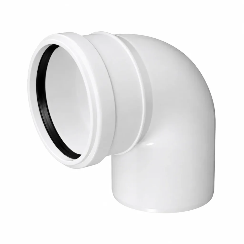
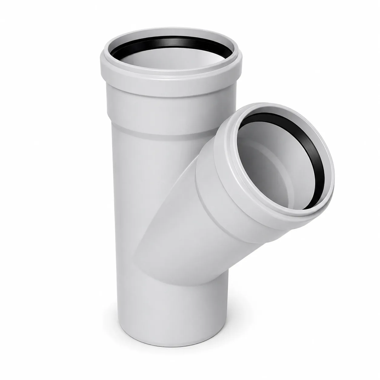
Junctions on branch pipes of about the same diameter should be made with a sweep of 25mm radius or at 45°. Connection of branch pipes of 75mm diameter or more to a stack of equal diameter should be made with a sweep of 50mm minimum radius or at 45° (paragraph 1.17).
Two things follow that are worth saying out loud. First, it is an either/or: a properly swept 87° entry with the correct radius is compliant, and so is a 45° entry. The trade shorthand that every branch must be a 45 is an oversimplification of a rule that offers two routes. Second, the required radius doubles for the larger diameter class — 25mm for like-for-like small branches, 50mm minimum once you are at 75mm or above into an equal stack. A fitting that satisfies the first does not automatically satisfy the second.
This is also the clearest argument against forming a connection by cutting a hole in the stack wall and strapping a boss over it. A hole cut with a hole saw has no sweep at all; the branch meets the stack at a square shoulder. It may be watertight and it may pass a visual inspection, but the geometry the guidance asks for is simply not present, and the turbulence at that shoulder is what tends to show up later as noise and as deposition on the crotch of the joint. A moulded branch fitting has the radius formed into it.
Which part of the pipe wall the small branch enters
Branch pipes up to 40mm diameter joining branch pipes of 100mm diameter or greater should, if practicable, connect to the upper part of the pipe wall of the larger branch (paragraph 1.18).
This one sentence explains a phenomenon that trade forums discuss endlessly without ever citing it: a 40mm waste entering a 110mm horizontal run from above behaves markedly better than the same waste entering from the side. The larger pipe runs part-full. A side entry at the springing line sits at or below the flowing surface, so the small branch is periodically submerged by whatever is passing, and each passing slug pressurises then depressurises it. Entering the upper part of the wall keeps the small branch above the flow and gives it a free air path.
Note the hedge in the source: “if practicable”. This is a preference, not an absolute, and it applies to branches joining larger branches. But where you have the choice, taking the small waste in high is free, and it is the cheapest siphonage insurance on the drawing.
Bends inside the branch itself
Bends in branch pipes should be avoided if possible; where they cannot be, they should have as large a radius as possible (paragraph 1.16). Each tight bend in a short unvented branch adds resistance in exactly the place where the design has least margin, and it is worth remembering that bend count also carries a ventilation consequence — a branch with more than five bends triggers a larger vent size, as the next section covers.
Why it gurgles: self-siphonage, induced siphonage and crossflow
A gurgling trap and an intermittent drain smell are the same complaint from the occupant and three different faults from the designer’s chair. Approved Document H names the underlying cause plainly: pressure fluctuation breaks the water seal, and the branch discharge pipes are designed the way they are precisely to prevent it (paragraph 1.5). Every trap has to retain at least 25mm of seal under working and test conditions (paragraph 1.3), so any mechanism that removes more than the margin between the installed seal depth and that 25mm floor lets sewer air into the room.
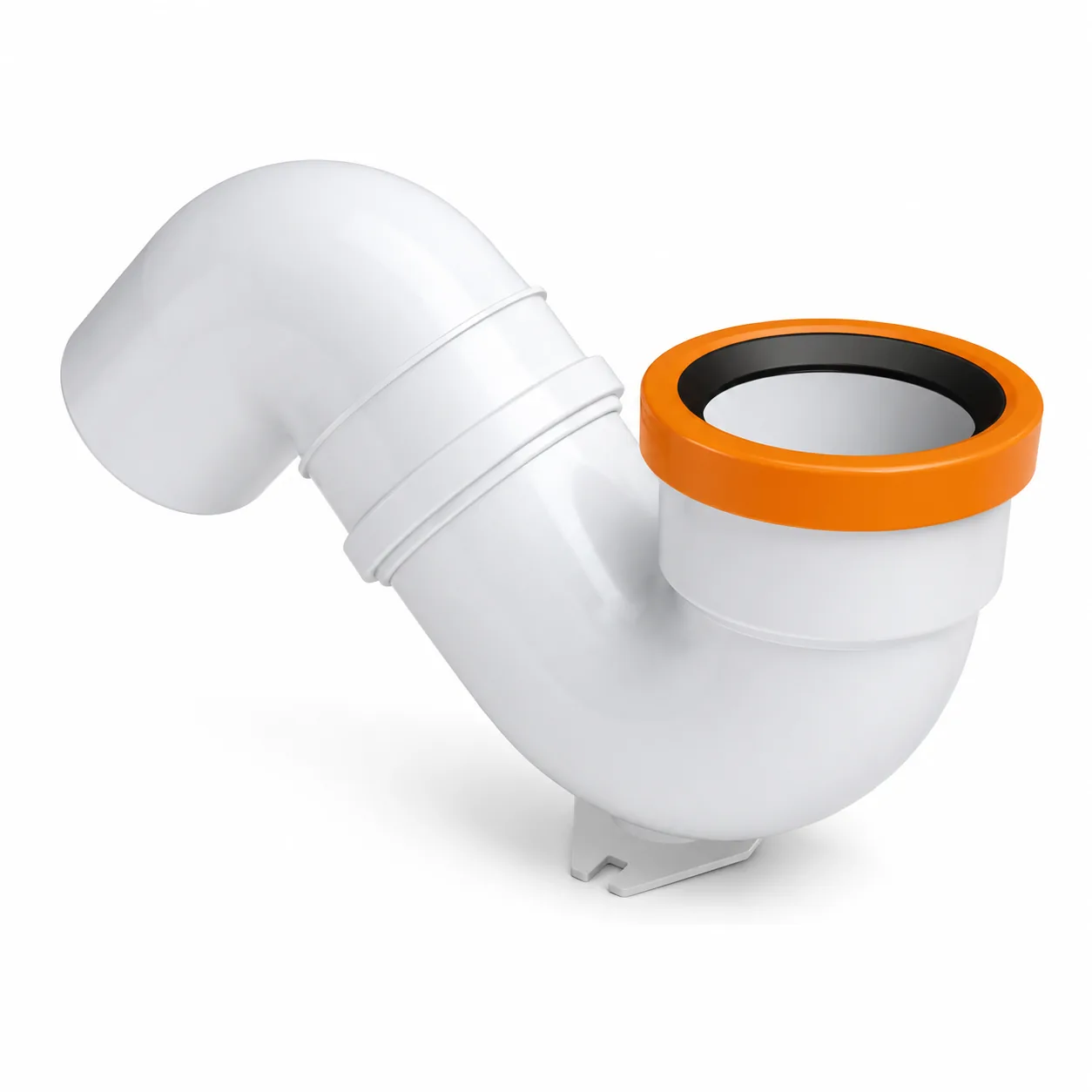
The margin is smaller than people assume. A bath or shower trap holds a 50mm seal (Table 1) — it can afford to lose 25mm and no more. A basin, sink, washing machine or dishwasher trap holds 75mm, so it has 50mm of headroom. That difference is why a shower trap is usually the first thing in a bathroom to start smelling.
Self-siphonage: the appliance empties its own trap
The appliance discharges, the branch runs full bore, and the moving slug of water drags the trap contents out behind it. Nothing else in the building has to be running. This is the failure the Table 2 length and gradient limits exist to prevent, and it is why the permitted length shortens as the fall steepens.
How to recognise it: the gurgle happens at the end of that appliance’s own discharge, every time, with nothing else in use. A basin that glugs as the last of the water goes down is self-siphoning.
What to check: measure the branch length and the fall, and read them against Table 2. If the branch is over length for its fall, the options are to reduce the fall into the permitted band, shorten the run, upsize the pipe, or vent the branch.
Induced siphonage: the stack pulls a neighbour’s trap
Discharge from somewhere else — typically a WC or a bath on the floor above — falls down the stack past the mouth of your branch. The falling column of water entrains air and generates negative pressure at the branch mouth, and that suction lifts the trap seal out from the room side.
How to recognise it: the affected trap gurgles when a different appliance is used, usually one higher up the building, and stays quiet when its own appliance runs. An occupant reporting “the shower smells whenever the flat upstairs flushes” is describing induced siphonage precisely.
What to check: whether the stack is adequately ventilated, and whether the branch is inside an exclusion zone — too near the bend at the foot (paragraph 1.11, paragraphs A.5 and A.6) or too near an offset (paragraph 1.27). This one is rarely fixed at the branch; it is usually a stack ventilation problem.
Crossflow: discharge entering the wrong branch
The third mechanism is not siphonage at all and is often misdiagnosed as a blockage. Discharge from one branch crosses the stack and enters the mouth of an opposing branch, which paragraph 1.10 prohibits outright.
How to recognise it: water appears in a fixture, or backs up in it, when a different fixture on the opposite side of the stack at a similar level is used. There is no gurgle and no smell — there is water where water should not be.
What to check: the vertical separation between opposing branch entries, and whether the two should be combined into a single double-branch fitting instead.
The diagnostic shortcut. Ask the occupant one question: does it happen when you use this fixture, or when someone uses a different one? Own fixture means self-siphonage and the answer is in Table 2. Different fixture, gurgling and smell, means induced siphonage and the answer is in the stack ventilation. Different fixture and visible water means crossflow and the answer is the branch entry geometry.
When the branch needs its own ventilation or an AAV
If the figures in Table 2 and Diagram 3 are exceeded, the branch pipe should be ventilated — by a branch ventilating pipe to external air, to a ventilating stack, or internally by use of an air admittance valve (paragraph 1.20). Three routes, and they are not equivalent in cost or in constraint.
Where the vent connects, and how big it has to be
A branch ventilating pipe should be connected to the discharge pipe within 750mm of the trap, and should connect to the ventilating stack or the stack vent above the highest spillover level of the appliances served. The ventilating pipe should have a continuous incline from the discharge pipe to the point of connection (paragraph 1.22).
That 750mm is the number that most often kills a retrofit. It is measured from the trap, not from the stack, so the vent has to be picked up right at the appliance — typically inside a vanity unit or behind a panel. On a design that has already been coordinated, finding a route out of that specific 750mm window and then rising continuously to above spillover level is frequently harder than upsizing the branch would have been.
Sizing: a branch ventilating pipe serving one appliance should be at least 25mm diameter, or at least 32mm where the branch is longer than 15m or has more than five bends (paragraph 1.24). Where a vent runs direct to outside air it should finish at least 900mm above any opening into the building nearer than 3m (paragraph 1.23) — the termination rules are covered in full in our guide to soil pipe vent termination heights.
Air admittance valves, and their four restrictions
An AAV is the internal option, and it is genuinely useful because it needs no external termination. Approved Document H accepts them where they comply with BS EN 12380:2002, subject to four conditions (paragraph 1.33):
- They must be located in areas which have adequate ventilation.
- They must be accessible for maintenance and removable to give access for clearance of blockages.
- They must not be used outside buildings or in dust-laden atmospheres.
- They must not adversely affect the ventilation the below-ground system needs, which is normally provided by open stacks.
That last condition is the one that gets missed on refurbishments. An AAV admits air but cannot relieve positive pressure. Where a drainage system ends up with no open ventilation at all — every stack capped with a valve — the guidance says alternative arrangements to relieve positive pressure should be considered. A building where every stack has been valved is not a building with cheap ventilation; it is a building with a pressure problem waiting for a surcharge event.
The “accessible and removable” requirement also rules out the common temptation to bury a valve in a sealed boxing. If it cannot be reached, it does not comply, however well it works on the day.
A worked example: three appliances into one stack
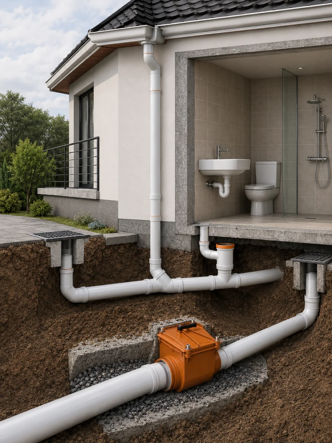
A first-floor bathroom in a three-storey house discharges to a 110mm stack on the external wall. Three appliances, three branches, all currently drawn at a builder’s-eye fall of roughly 45mm per metre because that is what fits the joist depth.
The WC, 1.2m from the stack, 100mm branch. Table 2 permits up to 8 WCs with outlets over 80mm on a 100mm branch up to 15m at 18–90mm per metre. At 1.2m and 45mm per metre this passes with enormous margin. WC branches are almost never the problem.
The bath, 1.8m from the stack, 40mm branch. The trap is 40mm with a 50mm seal (Table 1), so the branch must be at least 40mm (paragraph 1.15), and with only 25mm of seal to lose before it breaches the paragraph 1.3 floor it is the appliance in this bathroom most likely to smell first. But note what Table 2 does not contain, because it is the most-missed point on this page: there is no bath row, no shower row and no sink row. Table 2 covers WCs, urinals and washbasins or bidets only. For a bath, shower or sink branch, paragraph 1.19 sends you to Diagram 3 instead — the length and slope limits for those appliances are given graphically, not as a table row.
This is worth pausing on, because it is the single most common way an otherwise careful specifier gets this wrong. The washbasin figures are the ones every article quotes, they are easy to find, and they belong to an appliance with a 32mm trap on a 30mm-minimum pipe. Reaching for them to size a 40mm bath or sink branch borrows limits from a smaller pipe with a deeper seal — conservative in some respects, wrong in others, and in neither case the figure the guidance actually gives. Read Diagram 3 for those three appliances rather than extrapolating from the basin rows, and read it in the published document rather than from a summary, because the diagram is where the numbers live.
The basin, 2.4m from the stack, 32mm branch. This one fails, and it fails badly. On the washbasin row at 18–44mm per metre the limit is 1.1m, whatever the pipe measures — 32mm installed clears the 30mm minimum but buys no extra length, because the length limit attaches to the row, not to the millimetre. The branch is 2.4m. It is more than double the permitted unventilated length, and dropping the fall to the gentlest 18–22mm band only buys 1.7m — still short. The basin will self-siphon.
The two ways to fix the basin, and which one to choose
Option one, upsize: take the branch to 40mm and the limit becomes 3.0m at 18–44mm per metre. The 2.4m run passes with 600mm to spare, at the same fall already drawn. Cost is one pipe size on a 2.4m run and a reducer at the trap. No extra penetrations, no coordination.
Option two, vent: keep 32mm and add a branch ventilating pipe, connected within 750mm of the basin trap, minimum 25mm diameter, rising continuously to above the spillover level of the appliances served. Cost is a vent pipe, a route through a wall or ceiling void, and the coordination to get it there from inside the vanity.
For this layout, upsizing is the obvious answer and it is one line on the schedule. Venting earns its place when the run is genuinely long — past the 4.0m that 50mm buys you — or when the fall cannot be brought into the band for other reasons. As a rule of thumb worth testing against your own projects: check upsizing first on any branch under about 4m, and treat branch ventilation as the answer for the ones that remain.
The resulting connection schedule
- WC: 100mm branch, 1.2m, 45mm/m fall. Compliant unventilated. Swept entry at 50mm minimum radius or 45° (paragraph 1.17).
- Bath: 40mm branch, 1.8m. Verify against the bath row and hold the fall in the permitted band. 50mm seal — least margin in the room.
- Basin: upsized to 40mm, 2.4m at 18–44mm/m. Compliant unventilated at 3.0m limit.
- All three entries: above 450mm from the invert of the tail of the bend at the foot of the stack (paragraph 1.11), vertically separated so no two oppose each other (paragraph 1.10), and small branches into the upper part of the wall where they join a larger run (paragraph 1.18).
- On completion: air test at 38mm water gauge for 3 minutes, every trap retaining at least 25mm (paragraph 1.38).
Proving the branch complies, and specifying the fittings that let you
Designing it right and being able to demonstrate it are different jobs, and the second one is what a building control officer or a client’s engineer will actually ask for.
The test the finished pipework has to pass
The pipes, fittings and joints should be capable of withstanding an air test of positive pressure of at least 38mm water gauge for at least 3 minutes, and every trap should maintain a water seal of at least 25mm (paragraph 1.38). Smoke testing may be used to identify defects where a water test has failed — but smoke testing is not recommended for PVC-U pipes, which is worth knowing before someone reaches for a smoke pellet on a plastic stack.
Workmanship is referenced to a named standard rather than left to judgement: BS 8000 Part 13, the code of practice for above ground drainage (paragraph 1.37). That is a citable line on a specification.
What makes a compliance case checkable on a drawing
The air test proves the installation is sound. It does not prove the branch lengths were ever within Table 2 — a badly proportioned branch passes an air test perfectly well and siphons in service. The Table 2 case is a design case, and it is only checkable if the drawing carries the three things the table needs: branch diameter, developed length from trap to stack, and design fall in mm per metre.
Most residential drainage layouts carry the first and neither of the other two. Adding developed length and fall to each branch on the schedule costs nothing at design stage and converts an unverifiable drawing into one where anybody can read a row of Table 2 against it. Where a branch is over length and has been resolved by upsizing, note the original run so the reason for the larger pipe is on the record; where it has been resolved by venting, note the vent size and its connection point relative to the trap.
What to require of the fitting range so the geometry is achievable
Every geometric rule above assumes you can actually buy a fitting that forms it. In practice that means asking three questions of any drainage range before you specify it, whoever supplies it:
- Are the branch angles moulded, and which are available? The sweep at the crotch of a moulded branch is what delivers paragraph 1.17. A range offering 45° and 87° branches gives you both compliant routes; a range that only offers one leaves the geometry to site improvisation.
- Does the size range cover both the stack and the smallest waste? A branch schedule that stops at DN 110 forces adaptors at every fixture, and every adaptor is a joint and a potential step in the bore.
- Are single and double branches both available? The double branch is the compliant answer to the opposing-connection problem in paragraph 1.10, and if it is not in the range the crossflow risk comes back as a site decision.
Bekaatherm’s PP drainage and soil pipe system is built to EN 1451-1 and covers DN 50–200, with 45° and 87° elbows and both single branches (article codes BK-319–330, 50×50 up to 200×200) and double branches (BK-337–349, 50×50 up to 110×110), plus 45°/87° siphon traps at DN 50–110. The system design, stack and branch sizing and gradients are set by the designer under EN 12056, not by the fitting range — the range’s job is to make the geometry the designer specified buildable without adaptors. For the jointing choice that sits alongside this, see ring-seal versus solvent-weld drainage joints, and for the material standard itself, EN 1451 for PP soil and waste.
Where the published numbers stop
Everything above is public and checkable. The commercial terms are not, and it is more useful to say so than to guess: they are project-specific. Minimum order quantity on a drainage range is normally set against the size mix rather than as a single figure — a container of DN 110 pipe and a spread of small branch fittings are different problems. Lead time depends on the size spread and whether the schedule is stock or moulded to a run. Neither is a number that can honestly be published as one figure, and neither should be assumed from a catalogue.
The same applies to price structure and to sampling. Drainage is quoted per article code against a schedule, not at a headline rate per metre, because a stack schedule that is mostly DN 110 pipe and one that is mostly small branch fittings price very differently for the same total length — so the honest answer to “what does it cost” is that it is priced off your schedule, and the fastest way to a real number is to send the schedule.
On verification before commitment, this site publishes no self-service request form of any kind, so treat the published certification scopes as the evidence available up front; anything beyond that is agreed case by case within a project conversation rather than ordered from a page. Anyone who quotes a firm MOQ, price or lead time for a mixed drainage schedule before seeing the schedule is guessing.
Certification is documented separately: the system carries SKZ, CE, ISO and WRAS marks, and the specific scopes and certificate references are on the certifications page rather than reproduced here, because a certificate reference quoted second-hand in an article is exactly the thing that goes out of date without anybody noticing.
Specifying a drainage stack and want the branch schedule checked against the range?
For specifiers, M&E contractors and distributors working on a project stack — not for one-off fixture repairs, where your local merchant will serve you faster. Send the branch schedule (diameters, developed lengths, falls) and we will tell you which single and double branch article codes cover it, and where the schedule needs an adaptor because the geometry does not exist in the range.
What to do with this on your next drawing
The whole of the above collapses into a short sequence you can run against any branch on a layout, in roughly the order that catches problems earliest:
- Size from the trap, not from habit. The branch is at least the appliance trap diameter (paragraph 1.15). Write the trap seal depth next to it — 50mm appliances have half the margin of 75mm ones.
- Add developed length and fall to the schedule. Without those two columns nobody can check the branch against anything, including you in six months.
- Read it against Table 2 — or Diagram 3 for baths, showers and sinks. If it is over length, try upsizing before you try venting.
- Check where it lands. Above the clearance for your building height, not opposing another branch, not within 750mm of an offset.
- Specify the entry, do not leave it to site. Swept radius or 45° per the diameter class, small branches into the upper wall.
- Confirm the jurisdiction before issuing. These are England’s figures. Elsewhere, check them against your local code or EN 12056.
The branch that fails is almost never the one somebody worried about. It is the basin at the far end of a bathroom, on the smallest pipe in the room, drawn at whatever fall the joists allowed. Check that one first.
Frequently asked questions
Can you connect a waste pipe to a soil pipe?
Yes. Branch pipes should discharge into another branch pipe or a discharge stack unless the appliances discharge to a gully, and they should never discharge into an open hopper (AD H paragraph 1.7). The constraints are on length, fall, entry position and geometry, not on whether the connection is permitted.
How do I connect a 32mm waste pipe to a soil pipe?
A 32mm branch serves a washbasin or bidet (32mm trap, 30mm minimum pipe). Unventilated it may run 1.7m at 18–22mm per metre fall, 1.1m at 18–44mm, or 0.7m at 18–87mm (Table 2). Beyond that, upsize to 40mm for 3.0m or vent it.
How do I connect a 40mm waste pipe to a soil pipe?
40mm suits a bath, shower, sink, washing machine or dishwasher, matching the 40mm trap those appliances require (Table 1). For length and fall, read Diagram 3 rather than Table 2 — Table 2 has no bath, shower or sink row, and borrowing the 32mm washbasin figures for a 40mm appliance is the standard mistake. Where a branch up to 40mm joins a branch of 100mm or greater, connect to the upper part of the larger pipe wall where practicable (paragraph 1.18).
How close to the bottom of the stack can a branch connect?
No lower than 450mm above the invert of the tail of the bend at the foot of the stack, in single dwellings up to three storeys (paragraph 1.11). Up to five storeys it is 750mm; above five storeys, ground floor appliances need their own stack (paragraphs A.5 and A.6).
Why does my basin gurgle when the toilet upstairs is flushed?
That is induced siphonage: flow down the stack generates negative pressure at your branch mouth and lifts the trap seal. It is a stack ventilation or branch position issue, not a fault in the basin branch itself, and it is distinct from self-siphonage, where the trap empties during its own appliance’s discharge.
Does every branch connection need to be at 45 degrees?
No. Paragraph 1.17 allows either a sweep radius or a 45° entry: 25mm radius for junctions of about equal diameter, and 50mm minimum radius for branches of 75mm or more into an equal stack. A correctly swept 87° fitting is compliant.
When does a branch need an air admittance valve?
When the Table 2 length and gradient limits are exceeded and neither shortening nor upsizing is possible (paragraph 1.20). The valve must comply with BS EN 12380:2002, sit in a ventilated and accessible position, and must not be used outside buildings or in dust-laden atmospheres (paragraph 1.33).
Do these figures apply outside the UK?
Approved Document H is statutory guidance for England, and it is guidance rather than the Regulation itself. AD H names BS EN 12056 as an alternative compliance route (paragraph 1.39). Elsewhere, work to your local code or to EN 12056 directly; the figures here remain a useful design sanity check.