Key Takeaways
- DIN 8077 is dimensions. DIN 8078 is quality requirements and testing. Both are edition 2008-09 and both are still listed as current by DIN. Several top-ranking pages state this pair backwards.
- “PN 20” is not a property of the pipe. It is an SDR plus a safety-factor assumption. The same SDR 7,4 PP-R pipe rates 15,6 bar at safety factor 2,0, 20,4 bar at 1,5 and 24,5 bar at 1,25.
- Pipe series and SDR are the same geometry under two names: SDR = 2S + 1. S 2,5 is SDR 6, S 3,2 is SDR 7,4, S 5 is SDR 11.
- Wall thickness tolerance is plus only, never minus. The tabulated figure is a floor, not a target. A wall measuring over the chart is conforming; under is not.
- ISO 15874-2:2013 clause 6.2.2 sets a hard 2,0 mm minimum wall for anything joined by fusion. That silently deletes 16 mm and 20 mm pipe in the thinnest series from socket-welded work.
- ISO 15874-2:2013 now carries Amd 1:2018 and Amd 2:2022. A specification citing the plain 2013 text predates the impact-test amendment.
Two suppliers both answer your enquiry with “yes, DIN 8077 compliant”. Both are telling the truth. The pipe that arrives from each of them can still have a different wall thickness against the same purchase order, and neither supplier has done anything wrong.
That happens because a purchase order written as “25 mm PN 20 PPR” contains one number that describes geometry and one that describes an assumption. This article separates them. You get the dimension table, the formula that converts between every naming system in use, the tolerance rule that decides pass or fail, and the marking string that lets you check a real pipe against all of it with a tape measure and a caliper.
DIN 8077 and DIN 8078 do opposite jobs — and most pages have them swapped
Start here, because getting this wrong invalidates any citation you write downstream. The two standards are consecutive numbers covering the same material family — which is exactly why they get transposed.
DIN 8077:2008-09 is titled Polypropylene (PP) pipes — PP-H, PP-B, PP-R, PP-RCT — Dimensions. It is 33 pages, classified under ICS 23.040.20, and it is the geometry document: outside diameters, wall thicknesses, the series structure. It superseded DIN 8077:2007-05 as a corrected edition.
DIN 8078:2008-09 is titled Polypropylene (PP) pipes — PP-H, PP-B, PP-R, PP-RCT — General quality requirements and testing. It runs 17 pages and it is the conformity document: what the material has to do and how you prove it. It superseded DIN 8078:2007-05.
So the shape lives in 8077 and the proof lives in 8078. A currently ranking page on a major sourcing platform states the reverse — that 8077 covers material specification and 8078 covers dimensions. If you have been citing that page, your specification says the opposite of what you meant.
Neither document has been revised since September 2008. Write that edition date into your specification rather than the words “current edition”, and the document still says what you meant when someone reads it in three years.
Has EN ISO 15874 replaced DIN 8077?
Not replaced — layered. The German national standards remain published and current, and the European adoption of the international standard, ISO 15874-2:2013, sits alongside them with a harmonised dimension table. In practice the numbers agree. Cross-check the 20 mm S 2,5 row across the ISO table, a European manufacturer’s DIN 8077 reproduction and a technical catalogue and you get 3,4 mm in all three, to the tenth of a millimetre.
That agreement is what makes the table below usable no matter which standard your project cites. It is also the honest caveat on this article: the DIN documents themselves are paywalled, so what follows is the harmonised ISO 15874-2:2013 geometry that the DIN tables track, not a transcription of DIN clause numbering.
The wall thickness table, with the footnote competitors delete
Below is Table 5 of ISO 15874-2:2013, dimension class A, for PP-R. Outside diameter is given as a band — a minimum and a maximum mean diameter — and every figure in the series columns is the minimum wall thickness, written emin.
| Nominal OD (mm) | dem,min / dem,max | S 8 * | S 6,3 * | S 5 | S 4 | S 3,2 | S 2,5 | S 2 |
|---|---|---|---|---|---|---|---|---|
| 16 | 16,0 / 16,3 | 1,8 | 1,8 | 1,8 | 1,8 | 2,2 | 2,7 | 3,3 |
| 20 | 20,0 / 20,3 | 1,8 | 1,8 | 1,9 | 2,3 | 2,8 | 3,4 | 4,1 |
| 25 | 25,0 / 25,3 | 1,8 | 1,9 | 2,3 | 2,8 | 3,5 | 4,2 | 5,1 |
| 32 | 32,0 / 32,3 | 1,9 | 2,4 | 2,9 | 3,6 | 4,4 | 5,4 | 6,5 |
| 40 | 40,0 / 40,4 | 2,4 | 3,0 | 3,7 | 4,5 | 5,5 | 6,7 | 8,1 |
| 50 | 50,0 / 50,5 | 3,0 | 3,7 | 4,6 | 5,6 | 6,9 | 8,3 | 10,1 |
| 63 | 63,0 / 63,6 | 3,8 | 4,7 | 5,8 | 7,1 | 8,6 | 10,5 | 12,7 |
| 75 | 75,0 / 75,7 | 4,5 | 5,6 | 6,8 | 8,4 | 10,3 | 12,5 | 15,1 |
| 90 | 90,0 / 90,9 | 5,4 | 6,7 | 8,2 | 10,1 | 12,3 | 15,0 | 18,1 |
| 110 | 110 / 111 | 6,6 | 8,1 | 10,0 | 12,3 | 15,1 | 18,3 | 22,1 |
| 125 | 125 / 126,2 | 7,4 | 9,2 | 11,4 | 14,0 | 17,1 | 20,8 | 25,1 |
| 140 | 140 / 141,3 | 8,3 | 10,3 | 12,7 | 15,7 | 19,2 | 23,3 | 28,1 |
| 160 | 160 / 161,5 | 9,5 | 11,8 | 14,6 | 17,9 | 21,9 | 26,6 | 32,1 |
* The S 8 and S 6,3 columns carry a footnote in the source table: valid only for PP-RCT. They are not available in PP-R, and pages that reprint the table without the footnote are offering you a pipe that does not exist in the material you asked for.
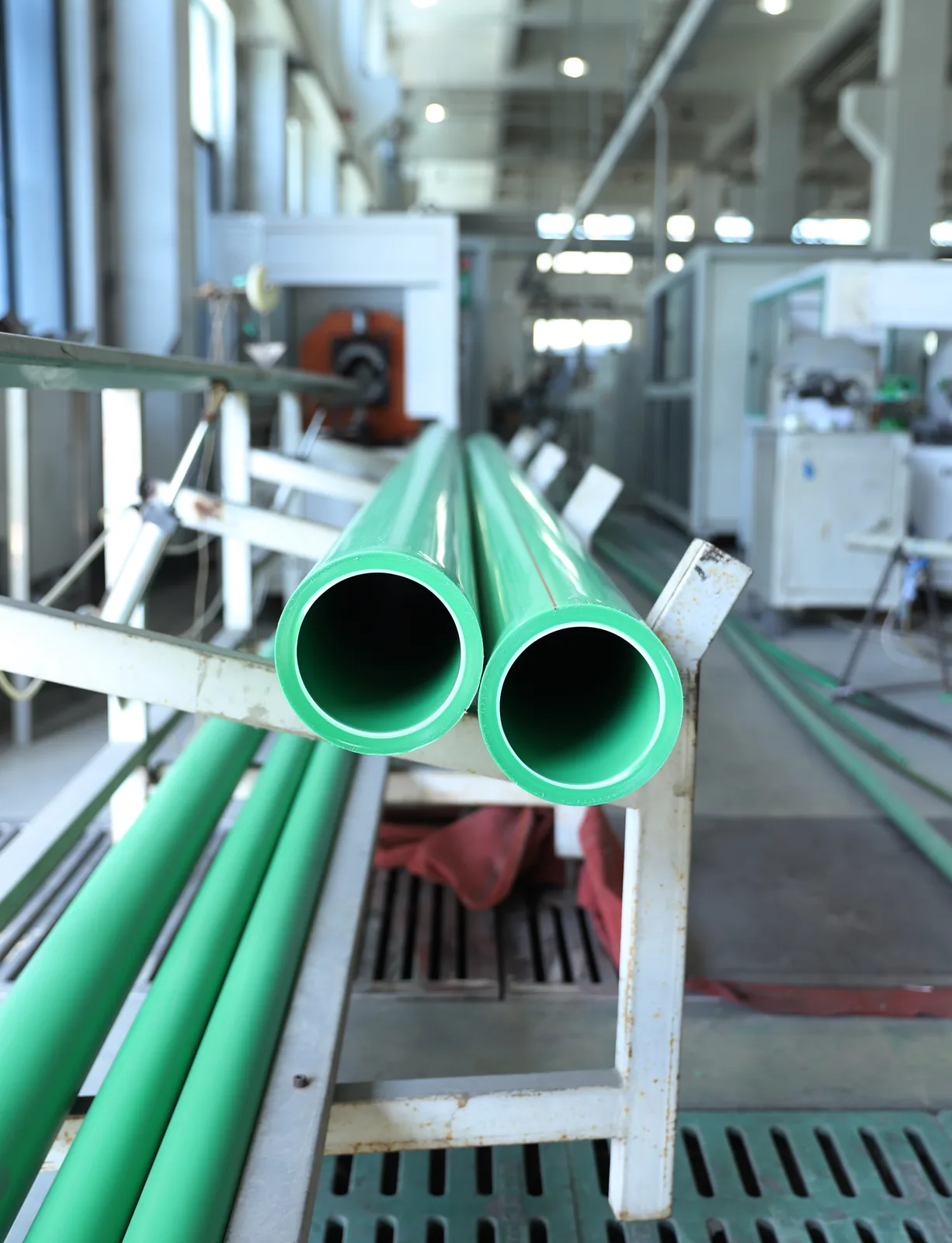
Read the 25 mm row across and the mental model falls into place. Outside diameter never moves — 25,0 to 25,3 mm, whatever the series. Only the wall grows, from 2,3 mm in S 5 to 5,1 mm in S 2. The bore shrinks to pay for it.
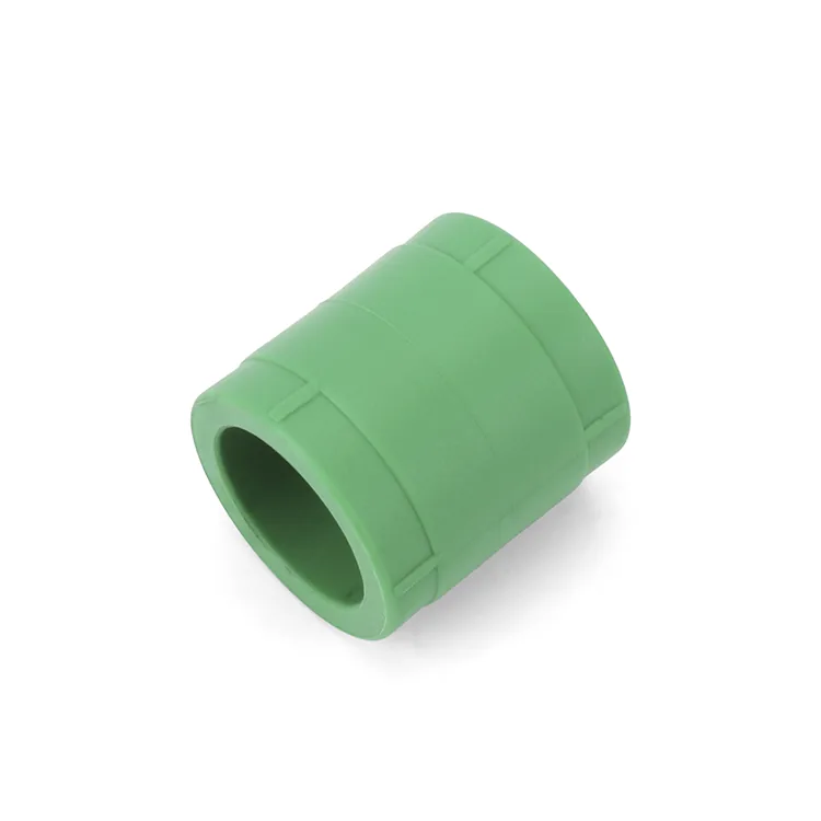
That is why a 25 mm PN 20 pipe and a 25 mm PN 10 pipe take the same socket fitting. The fitting grips the outside. It never sees the bore. It also explains why the diameter is written as a min/max band instead of a nominal figure with a plus-minus: the socket fusion joint depends on the outside surface landing inside a controlled window, and that window widens with size, from 0,3 mm at 16 mm to 1,5 mm at 160 mm.
S, SDR and PN: two are geometry, one is an assumption
Three naming systems circulate for the same product, and the confusion between them is not accidental — two describe the pipe and one describes a design decision made about the pipe.
Pipe series S and standard dimension ratio SDR are two labels for one geometry, tied by a fixed formula:
SDR = 2S + 1 and e = d / (2S + 1)
where d is outside diameter and e is wall thickness
Run it and the pairs drop out: S 2,5 = SDR 6, S 3,2 = SDR 7,4, S 4 = SDR 9, S 5 = SDR 11, S 6,3 = SDR 13,6, S 8 = SDR 17. Check it against the table above — 40 mm in S 2,5 gives 40 / 6 = 6,67, and the table says 6,7. The formula is the table.
PN is different in kind. It is a pressure, and to get a pressure out of a geometry you need a material stress and a safety factor — and the safety factor changed between standard editions while the pipe did not. Here is the same PP-R pipe rated three ways:
| Geometry | DIN 8077:1989, SF 2,0 | ISO 15874:2010, SF 1,5 | DIN 8077:2008, SF 1,25 |
|---|---|---|---|
| SDR 6 (S 2,5) | 20,0 bar — labelled PN 20 | 27,7 bar | 30,9 bar |
| SDR 7,4 (S 3,2) | 15,6 bar — labelled PN 16 | 20,4 bar | 24,5 bar |
| SDR 11 (S 5) | 10,0 bar — labelled PN 10 | 12,9 bar | 15,4 bar |
Maximum permissible working pressure for PP-R at 20 °C on a 50-year basis, per Table no. 9 of the Peštan PP-R technical catalogue. These are design-basis figures, not permission to operate a pipe at 30 bar.
Look at the left column and the legacy naming makes sense at last. PN 20, PN 16 and PN 10 are the safety-factor 2,0 numbers from the 1989 edition, and they are still printed on pipe today because the market memorised them. The pipe has not changed. The arithmetic applied to it has.
Now the practical consequence. If your PO says “PN 20” and your supplier designs to a modern safety factor, “PN 20” can be satisfied by SDR 7,4 — a thinner wall than the SDR 6 you pictured. On 25 mm that is the difference between 3,5 mm and 4,2 mm of wall, and both suppliers can point at a standard.
The fix takes four characters. Specify the geometry, not the label: write “25 × 4,2 mm, S 2,5 (SDR 6), PP-R, ISO 15874-2 dimension class A” instead of “25 mm PN 20”. A wall thickness in millimetres cannot be reinterpreted by a safety factor.
The 2,0 mm fusion floor deletes rows from the table
Clause 6.2.2 of ISO 15874-2:2013 carries a sentence that overrides the dimension table, and almost nobody reprints it: “However, pipes intended to be joined together by fusion shall have a minimum wall thickness of 2,0 mm.”
Go back to the table and apply it. The 16 mm and 20 mm sizes in S 8, S 6,3 and S 5 sit at 1,8 to 1,9 mm. Every one of those is below the floor. A specifier who reads only the dimension table can write a bill of materials for pipe that the same standard says cannot be socket-fused — and PPR is a socket-fusion system, so the pipe has no way to be installed.
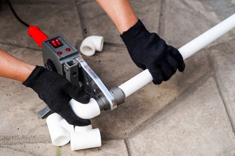
There is a physical reason behind the rule. Socket fusion melts a controlled depth from both faces and the molten material has to have somewhere to go. Below roughly 2 mm the heated zone runs through the full wall, the pipe end loses its stiffness against the heater bush, and the joint collapses inward instead of forming a bead. You get a joint that looks acceptable and has lost bore.
Best for / not for
The thin series — S 8 and S 6,3 — are best for PP-RCT systems in larger diameters where a thinner wall buys usable bore and the material’s higher temperature resistance carries the pressure. On 110 mm and up, moving from S 5 to S 6,3 is a real saving in weight and freight. They are not for PP-R at all, and not for 16 or 20 mm in any material if the joints are fused.
S 2,5 and S 3,2 are best for hot water and heating circuits in PP-R, which is why they dominate the market as PN 20 and PN 16 — the labels you will see on most of the PP-R pipe range on this site and everyone else’s. They are not for cold-water-only distribution at larger diameters, where you are paying for wall the duty never uses and losing bore that the pump has to make up.
Tolerance is plus only — which settles the most common inspection argument
Here is the rule that gets misapplied on both sides of an inspection. Wall thickness tolerance under ISO 15874-2:2013 Table 9 is expressed as +x mm with no negative limit, and it scales with the thickness itself.
| emin band (mm) | Tolerance | emin band (mm) | Tolerance |
|---|---|---|---|
| >1,0 to ≤2,0 | +0,3 | >6,0 to ≤7,0 | +0,8 |
| >2,0 to ≤3,0 | +0,4 | >7,0 to ≤8,0 | +0,9 |
| >3,0 to ≤4,0 | +0,5 | >8,0 to ≤9,0 | +1,0 |
| >4,0 to ≤5,0 | +0,6 | >9,0 to ≤10,0 | +1,1 |
| >5,0 to ≤6,0 | +0,7 | >10,0 to ≤11,0 | +1,2 |
ISO 15874-2:2013, Table 9. The footnote records that the level of these tolerances conforms to Grade V of ISO 11922-1.
First, the chart figure is a minimum and not a target. A 25 mm S 2,5 pipe measuring 4,4 mm against a tabulated 4,2 mm is conforming — it sits inside the +0,5 band. The complaint “your wall is thicker than the chart” is not a defect claim. It is a description of how the standard is written.
Second, there is no cushion downward. A pipe measuring 4,1 mm against a 4,2 mm minimum is non-conforming outright, with no tolerance to argue about. That is the check worth running on an incoming container, and it is the one that a supplier shaving material to hit a price will fail.
What we check before a dimensional claim leaves the plant
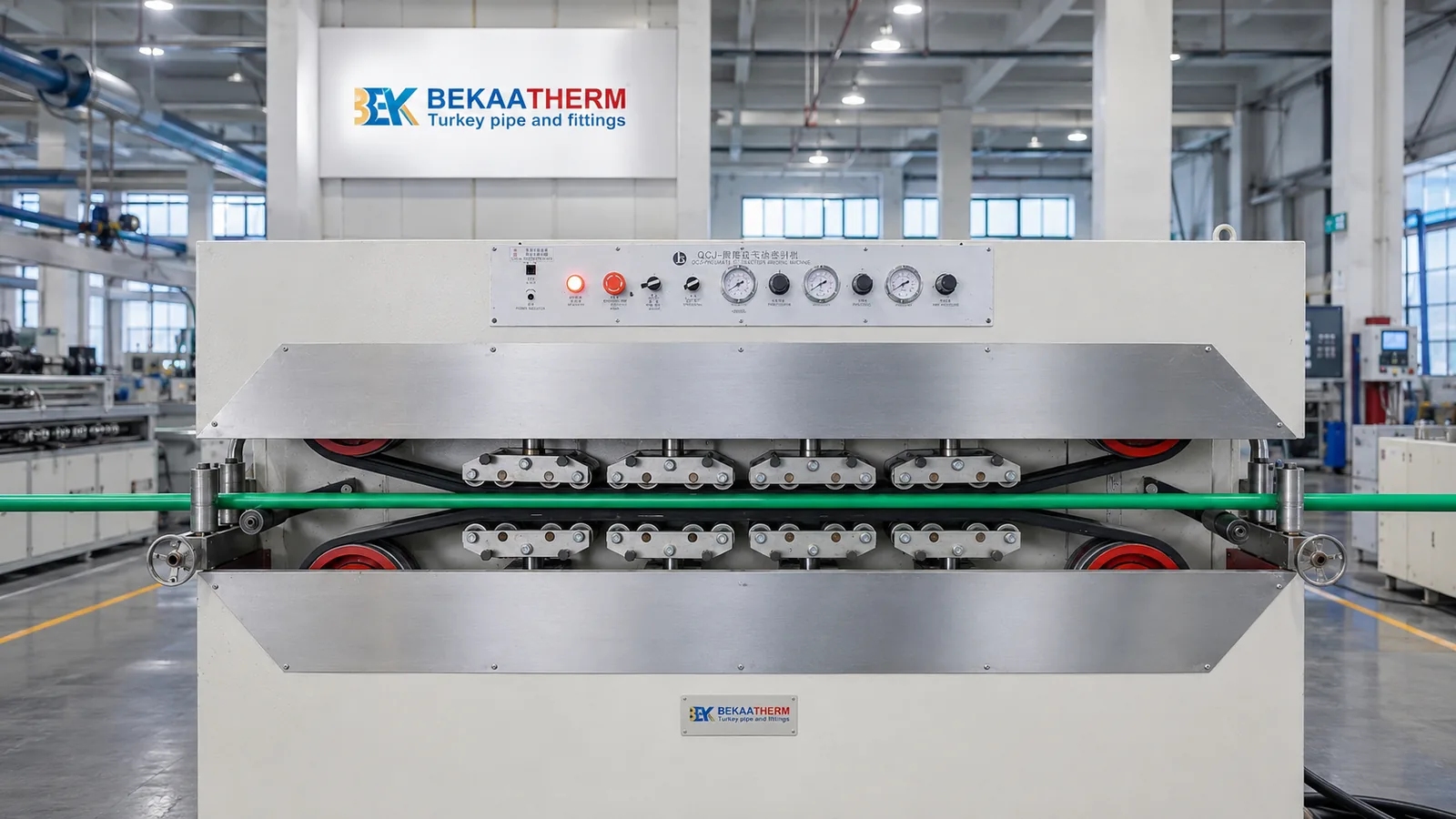
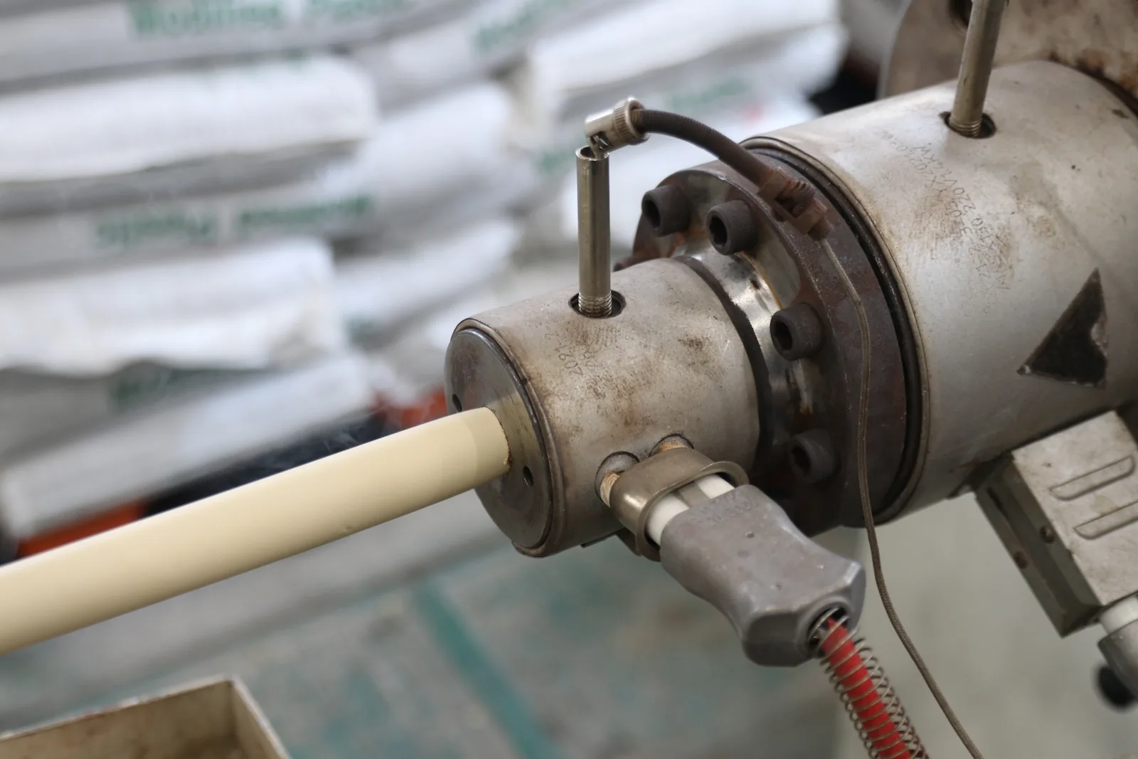
Because the tolerance is one-sided, dimensional control on a PPR line is a process problem rather than an inspection problem — you cannot sort your way to conformity after the fact. The sequence we run on our own extrusion, and the same sequence worth asking any supplier to describe:
- Outside diameter is set by the vacuum calibration tank, not the die. The die is oversized and the pipe is pulled down onto the calibration sleeve under vacuum. Diameter drift means a vacuum or water-temperature problem upstream, not a tooling problem.
- Wall thickness is the ratio of extruder output to haul-off speed. Speed up the haul-off and the wall thins across every point of the circumference at once. That is why line speed is logged against the size being run, not set by feel.
- Wall is measured at multiple points around the circumference, not once. A concentricity fault gives you a pipe that passes at 12 o’clock and fails at 6, and a single-point measurement finds it only by luck.
- Colour and dimension are held to one production allocation per project. Splitting a project across two production runs is where batch-to-batch variation enters, and on a site with visible pipework it shows up as a colour mismatch long before anyone measures a wall.
- The marking string is set from the works order, then verified on the first metre off the line. A correct pipe carrying a wrong marking is a non-conformity in its own right under clause 10.
Working out which series your project actually needs? If you are a specifier or consulting engineer sizing a PP-R system rather than sourcing one today, our PP-R pipe range page lists the sizes, series and colour options we run, so you can check that the geometry you are about to write into a specification is something the market actually produces.
You do not pick a PN — you pick an application class and a design pressure
This is the selection method the standard actually specifies, and it runs backwards from how most enquiries are written. Clause 6.2.2 of ISO 15874-2:2013 puts it this way: the minimum wall thickness shall be chosen so that the corresponding S series is equal to or less than Scalc,max for the duty. Lower S means thicker wall, so the rule is a ceiling on thinness.
The inputs are an application class — a service condition profile covering temperature and duration over the design life — and a design pressure in bar. The output is the maximum S you are allowed to use.
| Design pressure pD | Class 1 | Class 2 | Class 4 | Class 5 |
|---|---|---|---|---|
| PP-R — Scalc,max (Table 3) | ||||
| 4 bar | 6,9 | 5,3 | 6,9 | 4,7 |
| 6 bar | 5,0 | 3,5 | 5,5 | 3,2 |
| 8 bar | 3,8 | 2,6 | 4,1 | 2,4 |
| 10 bar | 3,0 | 2,1 | 3,3 | 1,9 |
| PP-RCT — Scalc,max (Table 4) | ||||
| 4 bar | 8,2 | 8,2 | 8,2 | 7,3 |
| 6 bar | 6,1 | 5,7 | 6,1 | 4,9 |
| 8 bar | 4,5 | 4,3 | 4,6 | 3,7 |
| 10 bar | 3,6 | 3,4 | 3,7 | 2,9 |
Maximum permissible S values from ISO 15874-2:2013 Tables 3 and 4. Lower S means a thicker wall, so a smaller figure in this table is a stricter requirement.
Work an example. A Class 2 hot water service at 6 bar design pressure in PP-R gives Scalc,max = 3,5. Your pipe must be S 3,5 or lower, so S 3,2 qualifies and S 4 does not. On 25 mm that is 3,5 mm of wall, not 2,8 mm — and note that the S 3,2 you just selected is the pipe the market calls PN 16, not PN 20.
Now compare materials at the same duty. Class 2 at 6 bar in PP-RCT allows S 5,7, so S 5 passes where PP-R needed S 3,2. Same service, thinner wall, larger bore, less material. That is the real argument for PP-RCT in larger diameters, and it is quantified right there in the two tables rather than asserted in a brochure.
One caution on reading these tables at all. Application classes and design pressures are set by the national installation rules that apply to your project, and those vary by market and building type. Confirm the class with the authority or approvals body that governs the installation before you fix a wall thickness — this table tells you what the product standard permits, not what your local code requires.
What changed: the two amendments nobody is citing
ISO 15874-2:2013 remains the current edition and was confirmed on review in 2023. But it no longer stands alone. Two amendments have been published against it: Amd 1:2018, and Amd 2:2022, whose published title is Impact test. In the UK the consolidated text is issued as BS EN ISO 15874-2:2013+A2:2022.
A revision is also in the pipeline — ISO/AWI 15874-2 is under development and is intended to replace the 2013 edition. No date is fixed, so treat it as a reason to re-check rather than a reason to wait.
The practical read: a specification, test report or declaration of conformity that cites plain “EN ISO 15874-2:2013” with no amendment reference was written against a text that predates the impact-test amendment. That does not make it wrong. It does make it worth asking which text the type testing was carried out against, particularly if the pipe will be handled or installed in cold conditions.
Read the marking string, not the invoice
Everything above becomes checkable the moment you have a pipe offcut in your hand, because the standard requires the pipe to declare itself. Clause 10.1 of ISO 15874-2:2013 requires marking printed or formed directly on the pipe not less than once per metre, legible without magnification, and where printed, in a colour that differs from the pipe body.
Table 12 sets out the minimum required content:
| Required element | Example / what to check |
|---|---|
| Number of the International Standard | ISO 15874 |
| Manufacturer’s name or trade mark | Should match the company on your invoice |
| Nominal OD × nominal wall thickness | 16 × 2,2 — check against the table above |
| Pipe dimension class | A — classes B1, B2 and C also exist |
| Material | PP-R — and not PP-RCT if you ordered PP-R |
| Application class with operating pressure | Class 1/10 bar — note: not a bare “PN 20” |
| Opacity, if declared | Relevant where the pipe is exposed to light |
| Manufacturer’s traceability information | Production year and month in figures or code, plus a site name or code where the manufacturer produces at more than one site |
That last row is the one buyers overlook, and it is the most useful. Where a manufacturer produces at more than one site, the marking is required to identify which site made the pipe. If you source from a supplier with more than one production origin, the pipe itself carries the answer.
Note also what the marking is required to say about pressure: application class combined with operating pressure, in the form Class 1/10 bar — not “PN 20” on its own. The standard resolves the ambiguity we started with by refusing to let the pipe carry the bare label.
A worked example on a real string
A PP-R marking reproduced in a European manufacturer’s technical catalogue reads:
PPRG1 EN15874 PPR-80 DN 40×6.7 PN20 A CLASS 1/10 bar S-2.5
Check it yourself in three steps. The string claims 40 × 6,7 mm — look up 40 mm in S 2,5 in the table above and you get 6,7 mm exactly. Then run the formula: SDR = 2(2,5) + 1 = 6, and 40 / 6 = 6,67, which rounds to 6,7. The geometry is internally consistent, so the marking is self-verifying.
The string carries both labels, PN20 and CLASS 1/10 bar — the standard’s format for the specifier, the legacy label for the merchant counter. Design against the second.
And a trap in the dimension class field
Class A is not the only dimension class. ISO 15874-2:2013 also defines class B1 and B2, whose sizes are based on copper pipe, and class C, for non-preferred sizes used in applications such as heating. Class B1 runs 10, 12, 15, 18, 22, 28 and 35 mm. Class C runs 14, 15, 16, 17, 18 and 20 mm, all at a 2,0 mm minimum wall.
So a 16 mm class A pipe and a 15 mm class B1 pipe are different products, and a diameter quoted without a class does not fully identify what you are buying. If your project is retrofitting into copper-sized fittings, that field on the marking string is the one that decides whether the delivery is usable.
What the dimensions are ultimately protecting
Every figure in this article is a 50-year, 20 °C number. That is not decoration — ISO 15874 is written around a 50-year design life at rated pressure and 20 °C, and the wall thicknesses in the tables are what delivers it. Our own 50-year warranty against material and manufacturing defects is matched to that 50-year design life, which is the only way a warranty on buried or embedded pipework means anything.
Which is also why a wall running 0,1 mm under the tabulated minimum is not a rounding question. The design life assumes the wall is there for fifty years of hoop stress.
We build our PP-R system to ISO 15874-1, -2, -3 and -5, and to EN ISO 15874, with DIN 8077 for dimensions and DIN 8078 for general quality requirements — the same pair this article started by separating. The system carries SKZ, ISO 15874, CE and WRAS certification, and 30 years of manufacturing across a 120,000 m² plant into 118+ countries is what keeps the same 98 items running to the same dimensions from one order to the next.
For engineers checking a specification against a real product range. If you have a schedule written in PN labels and want it translated into series, wall thicknesses and the sizes actually in production, send it over and we will return the geometry against each line. No commercial follow-up unless you ask for one — and if you are only after certification scope, the certifications page answers that without an email.
Send a schedule for a dimensional checkFrequently Asked Questions
What is the difference between DIN 8077 and DIN 8078?
DIN 8077:2008-09 covers dimensions of PP pipes — outside diameters, wall thicknesses and series. DIN 8078:2008-09 covers general quality requirements and testing. Many web pages state this pair backwards. Both editions are dated September 2008 and both are listed as current by DIN.
Is DIN 8077 still valid, or has EN ISO 15874 replaced it?
DIN 8077:2008-09 is still listed as current by DIN and has not been revised since September 2008. EN ISO 15874 sits alongside it with a harmonised dimension table rather than replacing it — the wall thickness figures agree to the tenth of a millimetre. Cite the edition date rather than “latest edition” in a specification.
Is PN 20 the same as SDR 6 or SDR 7,4?
It depends on the safety factor. SDR 6 PP-R rates 20,0 bar at safety factor 2,0, which is where the PN 20 label came from. The same pipe rates 27,7 bar at 1,5 and 30,9 bar at 1,25 — and at 1,25 the thinner SDR 7,4 already reaches 24,5 bar. Specify the wall thickness and series instead of the PN label.
How do I convert pipe series S to SDR?
Use SDR = 2S + 1. So S 2,5 is SDR 6, S 3,2 is SDR 7,4, S 4 is SDR 9, S 5 is SDR 11, S 6,3 is SDR 13,6 and S 8 is SDR 17. Wall thickness follows from e = d / (2S + 1), where d is the outside diameter.
What is the wall thickness of 25 mm PPR pipe?
It depends on the series. For 25 mm PP-R in ISO 15874-2:2013 dimension class A, minimum wall thickness is 2,3 mm in S 5, 2,8 mm in S 4, 3,5 mm in S 3,2, 4,2 mm in S 2,5 and 5,1 mm in S 2. Outside diameter stays between 25,0 and 25,3 mm in every case.
Is PPR wall thickness tolerance plus or minus?
Plus only. ISO 15874-2:2013 Table 9 expresses wall thickness tolerance as +x mm with no negative limit, from +0,3 mm on walls up to 2,0 mm to +1,2 mm on walls of 10,0 to 11,0 mm. The tabulated figure is a minimum, so a thicker wall conforms and a thinner one does not.
What is the minimum wall thickness for socket-fused PPR pipe?
2,0 mm. ISO 15874-2:2013 clause 6.2.2 states that pipes intended to be joined by fusion shall have a minimum wall thickness of 2,0 mm, regardless of the series table. This rules out 16 mm and 20 mm pipe in S 8, S 6,3 and S 5, which sit at 1,8 to 1,9 mm.
Why do 25 mm PN 20 and 25 mm PN 10 pipe use the same fittings?
Because outside diameter is held constant across all series. For 25 mm the mean outside diameter stays between 25,0 and 25,3 mm no matter which series you buy — only the wall thickness changes, and the bore shrinks to absorb it. Socket fittings grip the outside surface, so they fit regardless.
What should be printed on the pipe under ISO 15874-2?
Marking is required at least once per metre, legible without magnification, and must include the standard number, manufacturer’s name or trade mark, nominal diameter and wall thickness, dimension class, material, application class with operating pressure, opacity where declared, and traceability information including production year and month plus a production site identifier where the manufacturer uses more than one site.