Every page you will read on drainage pipe slope tells you two things: lay it at 1:40, and do not lay it too steep or the water will run away and leave the solids behind. The first is roughly right for one case out of several. The second is a claim the standards literature examined and rejected, and the UK body that approves sewers for adoption says almost the opposite in writing.
Key Takeaways
- There is no single correct drainage pipe slope. UK Approved Document H Table 6 gives 1:40 for a 100 mm foul drain under 1 L/s, but 1:80 once flow exceeds 1 L/s with at least one WC, and 1:150 for 150 mm with at least five WCs.
- Below ground, “too steep” is largely a myth. UK adoption guidance states its minima “should not to be taken as a norm when the topography permits steeper gradients”, and BS EN 752 cites evidence that steep gradients do not cause deposition of solids.
- Above ground it is real and codified: AD H Table 2 caps unventilated branch pipes at 90 mm/m, and a 30 mm washbasin waste may only run 0.7 m if laid at up to 87 mm/m, against 1.7 m at 18–22 mm/m.
- The four rulebooks disagree by about a third: 12.50 mm/m (UK, 1:80) against 10.42 mm/m (IPC, 1/8 in per foot) against 9.09 mm/m (German 1:DN for DN110) on the same 100–110 mm foul drain.
- The UK self-cleansing figure is 0.75 m/s at one-third design flow for foul sewers, and 1 m/s at pipe-full flow for surface water. Almost every secondary source drops the qualifier, which changes what the number means.
- A 450 mm invert drop over 30.0 m is 1.50%, or 1:67 — steeper than the UK 1:80, the IPC 1:96 and the German 1:110 minima, so it satisfies all three at once.
- Gradient is set by diameter and flow in every code here, never by polymer, so the same numbers apply to PP, UPVC and HDPE gravity drains of equal bore.
What the four rulebooks actually require
Start with the document most quoted and least read. Approved Document H, the 2015 edition, is the statutory guidance for England and Wales, and its Table 6 is titled “Recommended minimum gradients for foul drains”. The word doing the work is minimum — these are the flattest gradients at which drains should be laid, not the gradients at which they should be laid.
Table 6 has five rows, and the branching logic is on peak flow rather than diameter alone. Below 1 litre per second, both 75 mm and 100 mm drains take 1:40, with capacities of 4.1 and 9.2 L/s. Above 1 L/s, 75 mm drops to 1:80 (2.8 L/s) and 100 mm to 1:80 (6.3 L/s) — but the 100 mm row carries a footnote requiring a minimum of one WC. The 150 mm row allows 1:150 (15.0 L/s) with a minimum of five WCs.
Those footnotes are the part that gets lost. The flatter gradient is permitted because a WC flush delivers a slug of water big enough to move solids; take the WC away and the justification for 1:80 goes with it. AD H also sets a floor on bore: a foul-water drain should be at least 75 mm internal diameter, and one carrying WC or trade effluent at least 100 mm.
The same drain, priced in four currencies
The awkwardness for anyone buying or specifying across borders is that these rules are published in incompatible units. The UK writes ratios, the United States writes inches of fall per foot of run, Germany writes percentages and a rule keyed to the pipe’s own nominal diameter. Converted into one unit, the disagreement is visible and about a third wide.
| Code applied to a 100-110 mm foul drain | Minimum fall (mm/m) |
|---|---|
| UK AD H Table 6, 1 WC (1:80) | 12.5 |
| UK adoption fallback, 100 mm (1:80) | 12.5 |
| IPC 2024, 3-6 in (1/8 in/ft) | 10.42 |
| DIN 1:DN outside, DN110 | 9.09 |
The 2024 International Plumbing Code sets its minima in Section 704.1 and Table 704.1: 1/4 inch per foot for pipe 2.5 in and smaller, 1/8 inch per foot for 3 to 6 in, and 1/16 inch per foot for 8 in and larger. Section 704.1 also carries an exception that catches out commercial kitchens — where drainage piping runs upstream of a grease interceptor, the slope must be not less than 1/4 inch per foot, which the code itself glosses as a 2 percent slope.
The trap is the metric conversion, and it is a reading error rather than a publishing one. Table 704.1 is published in inches per foot only; the SI help sits underneath as a single unit rate — 1 inch per foot = 83.33 mm/m. That figure is correct, but it belongs to one inch per foot, a slope the table never actually requires. Read it as though it were the top row and you hand a metric site a drain four times steeper than the code asks for.
The row values are the ones to work from: 1/4 inch per foot is 20.83 mm/m, 1/8 inch is 10.42 mm/m, and 1/16 inch is 5.21 mm/m — each of them 83.33 scaled by the fraction in front of it.
The German rule worth stealing
German practice under DIN 1986-100 and DIN EN 12056 is the tidiest of the four, and the figures below are as set out in POLOPLAST’s dimensioning guide to those standards. Inside buildings, collection lines and building drains take a minimum fall of 0.5% with a minimum flow velocity of 0.5 m/s, sized at a filling degree of h/di = 0.5. Outside buildings the rule is simply 1:DN — the ratio is the pipe’s own nominal diameter, with a design velocity band of 0.7 to 2.5 m/s.
It is worth stealing because it scales without a lookup table. DN110 gives 1:110, which is 9.09 mm/m. DN160 gives 1:160, or 6.25 mm/m. DN200 gives 5.00 mm/m and DN250 gives 4.00 mm/m. The logic — bigger bore, flatter permissible fall — is the same logic behind the UK and US tables, but expressed as arithmetic instead of rows.
| Nominal size | UK AD H (foul) | IPC 2024 | German 1:DN (outside) | Fall over 30 m |
|---|---|---|---|---|
| 75 mm | 1:40 under 1 L/s; 1:80 above | 1/4 in/ft (1:48) | below recommended DN110 | 750 mm at 1:40 |
| 100–110 mm | 1:40 under 1 L/s; 1:80 above, min 1 WC | 1/8 in/ft (1:96) | 1:110 (9.09 mm/m) | 375 mm at 1:80 |
| 150–160 mm | 1:150, min 5 WCs | 1/8 in/ft (1:96) | 1:160 (6.25 mm/m) | 200 mm at 1:150 |
| 200 mm | see BS EN 752 for larger pipes | 1/16 in/ft (1:192) | 1:200 (5.00 mm/m) | 156 mm at 1:192 |
Rainwater is a separate schedule, and mixing it up with the foul table is a common drawing error. AD H paragraph 3.15 asks for not less than 1:100 on 75 mm and 100 mm rainwater drains, 1:150 on 150 mm, and 1:225 on 225 mm, referring larger pipes to BS EN 752-4. These are not in Table 6, and several published “gradient tables” online present them as though they were.
The “too steep” rule is mostly a myth — and exactly where it is not
Search this topic and you will meet the same sentence in a dozen forms: too much slope and the liquid outruns the solids, leaving them stranded to dry and block the pipe. It is stated confidently, usually without a source, and it drives real decisions — engineers flatten runs they did not need to flatten, and buyers argue about a gradient that was never the risk.
The research literature tested that belief and did not support it. Reviewing Swaffield and Marriott’s study of steep gradients between 30 and 90 degrees to the horizontal, Bokor concluded the study “put paid to the common belief that, due to water velocity tending to greatly exceed solid velocity, solids could become stranded” when transported along pipes laid at steep gradients. That review is peer-reviewed work published in the Journal of Environmental Protection in 2019.
More striking is where the counter-evidence sits. The same review records that a CIRIA report by Ackers, Butler and May is cited in BS EN 752 as evidence that steep gradients do not cause deposition of solids. The standard the drawing is designed to does not endorse the folklore repeated about it. One honest caveat, which the review itself makes: the Ackers report described its own approach as a “completely new methodology, unproven in practice”, and the reviewers note that this remains the case. The correct reading is not “steep is proven safe” — it is that the confident claim in the other direction has no support behind it.
What the adoption authority says in writing
The Sewerage Sector Guidance is the document a UK developer must satisfy for a sewer to be adopted. Its Appendix C, approved version 2.3 of 11 November 2023, sets the self-cleansing criteria — and then adds a sentence that ought to end the argument for below-ground work:
“These parameters should not to be taken as a norm when the topography permits steeper gradients. Hydraulic studies indicate that these requirements may not necessarily achieve a self-cleansing regime.”
That wording, typo and all, appears twice — once for foul sewers and once for surface water. It says two things at once: steeper is welcome where the ground allows, and the published minima may not deliver self-cleansing at all. The same document states elsewhere that steeper gradients are preferred to the use of backdrops at manholes. There is no reading of it in which a designer should be flattening a run to avoid stranding solids.
Where the limit is real, and codified
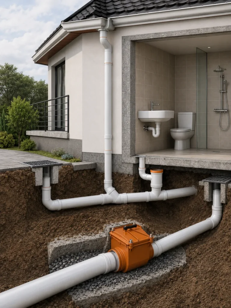
None of this makes gradient unbounded, and the exception matters more to a fittings buyer than the myth does. Above ground, on branch discharge pipes, an upper limit genuinely exists and is written into AD H Table 2 — which almost no page on this subject reproduces.
Table 2 gives gradient limits in millimetres of fall per metre, as a band. A WC branch on 100 mm pipe runs 18 to 90 mm/m, up to 15 m long, with up to eight WCs connected. A urinal trough on 65 mm runs the same 18 to 90 mm/m. The lower bound of 18 mm/m may be relaxed to 9 mm/m on long drain runs where space is restricted, but only where more than one WC is connected.
The instructive rows are the small-bore ones, because there gradient and permitted length trade against each other. A 30 mm washbasin or bidet waste may run 1.7 m at 18 to 22 mm/m. Allow it up to 44 mm/m and the permitted length falls to 1.1 m. Allow up to 87 mm/m and it drops to 0.7 m. Move to 40 mm pipe and you get 3.0 m at 18 to 44 mm/m; at 50 mm, 4.0 m.
| Gradient band permitted (mm fall per metre) | Max branch length (m), 30 mm pipe |
|---|---|
| 18 to 22 mm/m | 1.7 |
| 18 to 44 mm/m | 1.1 |
| 18 to 87 mm/m | 0.7 |
That is the real mechanism behind the folklore, and it is not about solids stranding on a steep fall. It is about a fast, thin stream in a small unventilated branch pulling the trap seal out behind it — which is why the constraint is a band tied to length and bore, and why it lives in the sanitary pipework section rather than the below-ground one. Our companion guide on soil and waste pipe system design rules covers the trap-seal side of that in detail.
Below ground, AD H limits steepness in exactly one place, and it is not about blockages either: for steeply laid drains up to 150 mm, velocity into a septic tank may be limited by laying the last 12 m at 1 in 50 or flatter. That protects the tank’s settlement process from turbulence. It is a tank-protection clause, not a pipe-protection clause.
Working it backwards: from invert levels to a gradient you can order
On site the question is rarely “what gradient should I use”. The levels are usually fixed at both ends — an existing manhole invert, a connection depth you cannot change — and the real question is whether what the ground gives you is legal. Work it in that direction.
The worked case
Take a 100 mm foul branch serving a small block: one WC among the appliances, so the AD H footnote for 1:80 is satisfied. The upstream invert is fixed by the building’s lowest connection, the downstream invert by an existing chamber. Measured, the drop is 450 mm over a run of 30.0 m.
Gradient is fall divided by length, in the same units. 0.450 m over 30.0 m is 0.015 — that is 1.50%, or 15.0 mm of fall per metre, or 1:66.7, which you would call 1:67 on a drawing. Nothing more complicated than a division is involved, and the three ways of writing it are the same number.
Now test it against all three rulebooks at once, which is the step usually skipped. Against AD H, the 100 mm foul drain with at least one WC needs 1:80 or steeper; 1:67 is steeper than 1:80, so it passes. Against the IPC, a 4 in drain sits in the 3-to-6 in band at 1/8 in per foot, which is 1:96; 1:67 is steeper, so it passes. Against the German outside-buildings rule, DN110 needs 1:110; 1:67 passes again. The run is legal under every code compared here, and it is legal with margin.
Then check the direction nobody checks: is 1:67 too steep? It is flatter than the 1:50 that AD H’s septic-tank clause treats as steep, and it is below ground, where neither AD H nor the adoption guidance sets an upper bound at all.
If this were a 100 mm branch discharge pipe above ground instead, the Table 2 band would apply — and 15.0 mm/m sits below its 18 mm/m lower bound, making the same run too flat for an unventilated WC branch. You would steepen it, ventilate it, or invoke the 9 mm/m relaxation, which needs more than one WC connected. Same number, opposite verdict, decided entirely by which side of the building wall the pipe is on.
The reverse question: what fall does a gradient cost you?
The other half of the calculation is depth, and it is what turns a gradient argument into an excavation cost. Fall equals length divided by the ratio. Over the same 30.0 m run, 1:40 needs 750 mm of fall, 1:80 needs 375 mm, 1:110 needs 273 mm, and 1:150 needs 200 mm.
| Gradient | Fall over 30 m (mm) |
|---|---|
| 1:40 (UK, under 1 L/s) | 750 |
| 1:80 (UK, 1 WC) | 375 |
| 1:110 (DIN, DN110) | 273 |
| 1:150 (UK, 150 mm) | 200 |
The spread between the ends of that list is 550 mm of extra depth at the downstream end, over a single 30 m run, for a decision that looks like a detail on a drawing. That is the difference between a connection that lands above an existing chamber invert and one that does not, and it compounds along every subsequent run. It is also why the adoption guidance’s “steeper where topography permits” is not an invitation to maximise — steeper is hydraulically fine and expensive to dig.
Checking a fall before you commit to a schedule
- Fix both invert levels first, then divide the drop by the run length. That is your actual gradient, in the units the drawing already uses.
- Identify which code has force at the site, not which one the drawing was drawn in. A UK-format drawing built to the IPC is checked against Table 704.1.
- Check whether the flat-gradient footnote applies — the UK 1:80 and 1:150 rows both depend on a minimum WC count, and without it you are back at 1:40.
- Separate foul from rainwater before comparing anything. They are different schedules in the same document.
- Above ground only, check the upper bound and the branch length together — 90 mm/m is the ceiling, and small-bore length shrinks as gradient rises.
- Convert once, into millimetres per metre, and put that number on the schedule. Most cross-border errors are unit errors, not engineering errors.
For specifiers and contractors pricing a PP soil and waste package against a fall schedule
Once the gradient is settled, the schedule is a fittings question: which branch angles, which siphons, which reducers, at what article codes. The Bekaatherm PP drainage range is published as a product schedule with BK-series article codes, referenced to EN 1451-1, the European product standard for PP soil and waste discharge pipework, with EN 12056 as the system design standard.
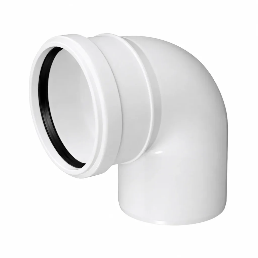
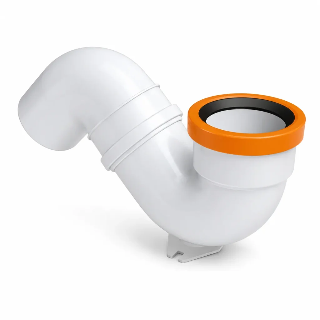
The schedule covers pipe in DN 160 and 200, elbows, branches and non-return valves across DN 50–200, siphons DN 50–110, and double branches from 50×50 to 110×110.
Two things worth knowing before you ask. There is no published minimum order quantity for this line — the order minimum is set per project against your own size mix — and the range is sold wholesale to importers, distributors and project contractors rather than as single-item retail. Dimensional questions on a specific connection go to the technical team directly.
The velocity number, and the qualifier everyone drops
Behind every gradient table is a velocity target, and this is where secondary sources quietly corrupt the figure. You will read that drains need 0.75 m/s, or that they need 2 feet per second, stated as a flat property of the pipe. Neither is quite what the source documents say, and the missing half changes the meaning.
The UK Sewerage Sector Guidance sets it precisely: to provide a self-cleansing regime within gravity foul sewers, the minimum flow velocity should be 0.75 m per second at one-third design flow. For surface water gravity sewers, the figure is 1 m per second at pipe-full flow. Those are two different velocities measured at two different flow conditions, and quoting either without its condition makes it uncheckable.
The guidance then does something unusually candid for a code document: it provides a gradient fallback for when the velocity criterion cannot be met. A 150 mm gravity sewer laid not flatter than 1:150 with at least ten dwellings connected satisfies it; so does a 100 mm sewer or lateral drain laid not flatter than 1:80 with at least one WC, or 1:40 where there is no WC. For surface water, 150 mm at 1:150 or 100 mm at 1:100.
| System | Velocity target | Measured at | Gradient fallback if not met |
|---|---|---|---|
| UK gravity foul sewer | 0.75 m/s | one-third design flow | 150 mm at 1:150 (10+ dwellings); 100 mm at 1:80 with a WC, 1:40 without |
| UK gravity surface water sewer | 1 m/s | pipe-full flow | 150 mm at 1:150; 100 mm lateral drain at 1:100 |
| German practice, inside buildings | 0.5 m/s minimum | filling degree h/di = 0.5 | 0.5% minimum fall on collection lines and building drains |
| German practice, outside buildings | 0.7 to 2.5 m/s band | design flow | 1:DN — the ratio is the pipe’s own nominal diameter |
Read those two paragraphs together and the structure of the whole subject appears. The gradient tables are not the requirement. They are a proxy for the requirement — a lookup that lets you avoid a hydraulic calculation — and the authority publishing them says in the next clause that the proxy may not achieve what it stands in for. German practice makes the same move with different numbers: 0.5 m/s minimum inside buildings at a filling degree of 0.5, and a 0.7 to 2.5 m/s band outside.
What actually blocks drains, if not the gradient
If steep gradients do not strand solids, something else is causing the blockages the folklore explains. The research points at two things, and both are more useful to a buyer than another decimal place on a fall.
The first is flush attenuation. Swaffield’s later position, quoted in the 2019 review, is that solid velocity depends on the surrounding flow conditions, and as the flush attenuates, deposition occurs. The consequence he draws is blunt: for one WC in one pipe of fixed slope, diameter and roughness, with no other supporting flow, there is a maximum travel distance for any solid regardless of how many times the WC is flushed. He stated it in respect of a 150 mm sewer at 1/100. Flushing again does not push the solid further; the water arrives, spreads out and no longer carries anything.
That reframes the design problem. The variable that matters on a long, lightly loaded run is not the gradient but whether any supporting flow arrives at all — which is why WC counts appear as footnotes in the UK table, and why low-flow modern fittings have made an old problem worse.
The half-millimetre that outweighs the argument
The second cause is the one worth carrying into a purchase decision. Littlewood’s finding, in the same review: “the movement of the solid was found to be very sensitive to joints and imperfections in the pipe. A displacement of less than 0.5 mm was found to affect the solid transport, particularly when the solid was moving with velocity of less than 0.25 m/s”. Bokor’s laboratory work concluded that poor quality control in jointing pipes directly resulted in solids being deposited prematurely.
Half a millimetre. A step smaller than the thickness of two sheets of paper, at a socket, measurably changes whether solids keep moving — while the industry argues about whether a run should be 1:80 or 1:67. For anyone specifying or importing, that is the actionable finding in this entire subject: socket geometry, seal seating and installed alignment carry more blockage risk than any gradient decision inside the legal band, and unlike the gradient they are properties you are buying rather than digging.
| Fall per metre demanded by each code, and the joint step that matters | Millimetres |
|---|---|
| 1:40 fall per metre | 25.0 |
| 1:80 fall per metre | 12.5 |
| IPC 1/8 in/ft per metre | 10.42 |
| 1:110 fall per metre | 9.09 |
| Joint step that affects transport | 0.5 |
It is also the argument for checking fittings physically before a first order. Root radius at a branch, socket depth and the seat the ring seal sits in are all verifiable on a sample, and the difference between a well-formed socket and a marginal one does not show up in a catalogue table. Our guide to ring-seal against solvent-weld drainage joints covers how the two jointing systems differ on exactly this point.
Reading a drawing across borders
Most of the confusion this article exists to clear up is not hydraulic. It arrives when a drawing crosses a border and keeps its original vocabulary while acquiring a new set of legal requirements.
The clearest example is the one already on the table. A German drawing marked Gefälle 1:DN for a DN110 line outside the building is asking for 9.09 mm/m. A UK drawing marked 1:80 for the nominally equivalent 100 mm foul drain is asking for 12.50 mm/m. Neither is wrong; they are different documents with different constants, and a drawing that keeps its original notation after the project changes jurisdiction is asking a contractor to satisfy a rule that no longer has force at the site.
The pattern to watch for is a familiar-looking rule carrying a different constant — and a qualifier attached to it that travels less well than the number does. The UK’s flatter gradients are conditional on a WC being connected; the German 1:DN rule is conditional on being outside the building, since inside it the minimum is 0.5% with a 0.5 m/s velocity check. Strip the qualifier and both numbers survive the trip looking authoritative while having quietly stopped meaning what they meant.
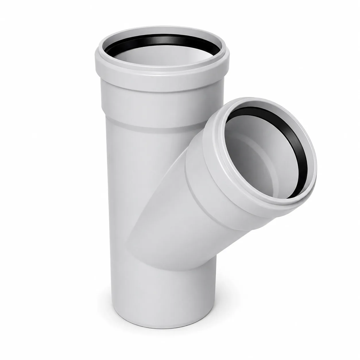
The material question, which buyers ask often, has a clean answer. Every code compared here specifies gradient by diameter and flow — never by polymer. AD H’s Table 7 lists UPVC to BS EN 1401 and PP to BS EN 1852 for below-ground gravity drainage, with application area code UD normally specified, and applies the same Table 6 gradients to both. So a PP drain, a UPVC drain and an HDPE drain of the same bore take the same fall.
Material choice is decided on noise, chemical and temperature resistance, jointing system and handling — not on gradient. Our comparison of UPVC drainage pipe under EN 1329 against EN 1401 sets out where the above-ground and below-ground product standards actually diverge, and the PP drainage system range shows how a schedule is put together once the fall is fixed.
What we check on a fall schedule, and where we stop
When a drawing arrives with a fall schedule attached, four things get checked before anything is quoted, and all four are answerable from the drawing itself.
First, which document has force at the site — not which notation the drawing uses, because on export work the two disagree more often than not. Second, whether each run’s stated gradient clears that document’s minimum for its diameter and its flow condition: AD H Table 6 branches on peak flow, so 100 mm is 1:40 below 1 L/s but 1:80 above it.
Third, whether the footnote survives. A 100 mm run at 1:80 needs a WC connected and a 150 mm run at 1:150 needs five, so a schedule that inherits the flat gradient without inheriting the appliances is the most common quiet error on a marked-up drawing. Fourth, whether the nominal sizes form one coherent family — gradient is specified per run, but what ships is branches, elbows and reducers at every change of direction, in DN110, DN160 or DN200.
Where we stop is worth stating plainly, because it is the boundary a supplier should not cross. We do not carry out the hydraulic design, we do not certify a gradient against a local authority’s requirements, and we do not substitute for the adoption process — the Sewerage Sector Guidance is explicit that its tabulated minima may not achieve self-cleansing conditions in every case, which is exactly the judgement a designer is engaged to make.
What a manufacturer can tell you is whether the pipe, the fittings and the jointing system you have specified exist in one size family, to the standards the code names — BS EN 1401 for UPVC and BS EN 1852 for PP below ground — in the quantities the run requires. The fall stays the designer’s number.
| This guide is for | This guide is not for |
|---|---|
| Specifiers checking a fall schedule against more than one national code | Anyone needing a signed hydraulic calculation for adoption — that is a Colebrook-White exercise with site data |
| Importers and distributors sizing a drainage package for a mixed-code export market | Pumped or vacuum drainage, siphonic roof systems and rising mains, which do not follow gravity gradient rules |
| Contractors reverse-checking a gradient from fixed invert levels | Domestic repair work where the existing fall is being matched rather than designed |
Watch a fall being set on site

The short version
Find the code with force at the site, read the minimum for your diameter and flow, check the footnote that the flat gradient depends on, and lay it at that or steeper. Below ground there is no upper bound worth worrying about, and the UK adoption authority prefers steeper where the ground allows. Above ground there is a real one — 90 mm/m on unventilated branches, with permitted length shrinking as gradient rises.
And when the gradient is settled, spend the remaining attention on the sockets rather than the second decimal place. Half a millimetre of joint misalignment moves solids more reliably than any argument about 1:67 against 1:80.
If you are checking a run before it becomes a schedule, three numbers settle it: the run length, the two invert levels, and the nominal size. Everything above is the arithmetic that turns those into a gradient a code will accept.
Frequently Asked Questions
What is the minimum slope for a 100 mm drainage pipe?
Under UK Approved Document H Table 6, 1:40 below 1 L/s peak flow, or 1:80 above it provided at least one WC is connected. The 2024 IPC asks 1/8 inch per foot (1:96) for 3-to-6-inch pipe, and German practice outside buildings asks 1:110 for DN110.
Can a drainage pipe be too steep?
Below ground, essentially no — UK adoption guidance says its minima should not be taken as a norm where topography permits steeper gradients, and BS EN 752 cites evidence that steep gradients do not cause deposition. Above ground, yes: AD H Table 2 caps unventilated branch pipes at 90 mm/m.
How do I convert 1:80 into millimetres per metre?
Divide 1000 by the ratio. 1:80 is 12.50 mm/m and 1.25%; 1:40 is 25.00 mm/m; 1:110 is 9.09 mm/m; 1:150 is 6.67 mm/m. For inch-per-foot figures, multiply by 25.4 and divide by 0.3048 — so 1/8 inch per foot is 10.42 mm/m.
What fall do I need over a 30 metre run?
Divide the run length by the gradient ratio. At 1:40 you need 750 mm, at 1:80 you need 375 mm, at 1:110 you need 273 mm and at 1:150 you need 200 mm — a 550 mm spread in excavation depth across that range.
Does PP drainage pipe need a different gradient from UPVC or HDPE?
No. Every code cited here specifies gradient by diameter and flow, never by material. AD H Table 7 lists UPVC to BS EN 1401 and PP to BS EN 1852 for below-ground gravity drainage and applies the same Table 6 gradients to both.
What is the self-cleansing velocity for a foul drain?
UK Sewerage Sector Guidance sets 0.75 m/s at one-third design flow for gravity foul sewers, and 1 m/s at pipe-full flow for surface water. The flow condition is part of the figure, and most secondary sources omit it.
Why do rainwater pipes use different gradients?
They carry no solids, so the design target is capacity rather than solid transport. AD H paragraph 3.15 asks not less than 1:100 for 75 mm and 100 mm, 1:150 for 150 mm and 1:225 for 225 mm — a separate schedule from the foul Table 6.
Written by Thomas, Export Manager at Bekaatherm — a Turkish manufacturer of PPR, HDPE, PP silent drainage and UPVC systems, with 30 years of manufacturing across a 120,000 m² plant and 1000+ staff, supplying 98 items across 4 systems to 118+ countries. Every gradient, velocity and dimensional figure on this page is cited to the issuing document — Approved Document H 2015, the 2024 IPC, Sewerage Sector Guidance Appendix C v2.3, and DIN 1986-100 — and linked to the source above; none of it is a Bekaatherm house figure. Published 2 September 2026.