Key Takeaways
- Stack sizing runs on one formula: Qww = K × √∑DU. You sum discharge units from an appliance schedule, multiply by a frequency factor for the building type, and match the result against a published stack capacity.
- A swept entry on a DN 100 stack carries 5.2 l/s against 4.0 l/s for a square entry — 30% more capacity from a fitting change, with no increase in diameter.
- Add a secondary vent and that same DN 100 stack reaches 7.3 l/s. Against a square-entry primary ventilated stack, that is an 82% capacity gain on identical nominal bore.
- EN 12056-2 sizes by minimum internal diameter, not outside diameter. DN 100 in the sizing tables means a bore of at least 96 mm — which is what a DN 110 outside-diameter pipe has to deliver.
- The same basin is 0.5 DU in System I and 0.3 DU in System III. Germany, Belgium and Ireland require System I, so the same building calculates differently depending on where it is built.
- EN 1329-1 was reissued on 5 May 2026 and now permits recyclate content up to 100%. “EN 1329 compliant” no longer implies virgin material — ask which formulation was type-tested.
Most soil stacks get specified at 110 mm because the last one was 110 mm. That works often enough to hide the times it doesn’t — and it gives you nothing to show a building control officer who asks how you arrived at the size.
EN 12056-2:2000, Gravity drainage systems inside buildings — Part 2: Sanitary pipework, layout and calculation, gives you the arithmetic instead. This article walks an appliance schedule through that calculation end to end, then checks the answer against the standard’s own capacity tables. That edition remains in force: it sits at CEN review-enquiry stage with a review completion date of 3 June 2026, and no replacement edition of Part 2 has been published.
First decide which system you are designing to
This is the step that gets skipped, and skipping it invalidates everything downstream. EN 12056-2 does not define one method — it defines four, and each assigns a different discharge unit value to the same appliance. They differ by how full the branch pipes are designed to run.
System I uses partly filled branch discharge pipes at a filling degree of 0.5, meaning the branch is sized to run half full. System II uses small bore branches at 0.7. System III uses full bore branches at 1.0, with each branch connected separately to the stack. System IV is the separate-stack variant: any of systems I, II or III split into a black water stack serving WCs and urinals and a grey water stack for everything else.
Your country usually decides for you. Annex A of the standard records national practice, and it is blunt about three markets: Germany requires drainage System I, Belgium permits only System I, and Ireland treats Drainage System No 1 as the accepted method for gravity drainage inside buildings. If you are shipping the same DN 110 pipe into all three, you are designing to System I in all three — which means the higher discharge unit column and the tighter gradient limits.
Best for / not for
System III is best for projects where every appliance gets its own connection to the stack and branch runs are short — it produces the lowest discharge units and the smallest pipe. It is not for a German, Belgian or Irish project, where national regulations put you in System I regardless of what the hydraulics would allow.
System I is best for conventional layouts where several appliances share a branch into the stack, and it is what most Continental European specifications assume. It is not for anyone trying to minimise pipe size on paper: a bath is 0.8 DU in System I against 0.5 DU in System IV, so the same building yields a bigger number.
The worked example: an 8-storey residential stack
Take a residential block of eight storeys with two apartments per floor sharing one stack. Each apartment has a bathroom with a WC on a 6.0 litre cistern, a wash basin, a bath, and a kitchen with a sink and a household dishwasher. That is 16 apartments on the stack. The building is in Germany, so System I applies.
Step 1 — Sum the discharge units
Table 2 of the standard assigns a discharge unit value in litres per second to each appliance, per system. Pulling the System I column for our five appliance types:
| Appliance | DU, System I (l/s) | Qty on stack | Subtotal DU |
|---|---|---|---|
| WC, 6.0 l cistern | 2.0 | 16 | 32.0 |
| Wash basin | 0.5 | 16 | 8.0 |
| Bath | 0.8 | 16 | 12.8 |
| Kitchen sink | 0.8 | 16 | 12.8 |
| Dishwasher, household | 0.8 | 16 | 12.8 |
| ∑DU | — | 80 appliances | 78.4 |
Step 2 — Pick the frequency factor
K accounts for the fact that 80 appliances never discharge at once. Table 3 gives four values: 0.5 for intermittent use such as a dwelling, guesthouse or office; 0.7 for frequent use such as a hospital, school, restaurant or hotel; 1.0 for congested use such as toilets or showers open to the public; and 1.2 for special use such as a laboratory.
A residential block is intermittent use, so K = 0.5. This single choice moves the answer more than any other input, and it is where optimistic design happens. A student residence or a hotel is not a dwelling — at K = 0.7 the same stack produces 40% more flow.
Step 3 — Run the formula
Qww = K × √∑DU = 0.5 × √78.4 = 0.5 × 8.854 = 4.43 l/s
Two rules bite here. If the building had a continuous flow — a cooling system bleed, a pumped discharge from a basement lifting plant — that flow is added on top as Qtot = Qww + Qc + Qp, with no square-root diversity applied. Continuous flows do not get the benefit of the doubt, because they are not intermittent.
And the design capacity can never fall below the flow rate of the single largest appliance. Our largest is the 6.0 litre WC at 2.0 l/s, comfortably below 4.43 l/s, so the calculated figure governs. On a small stack serving three basins, that rule is what stops you arriving at an absurdly small pipe.
Step 4 — Match the flow to a stack size
Now the part that competitor calculators hide. Table 11 gives the capacity of a primary ventilated stack in two columns — square entries and swept entries — because the geometry of the branch connection changes how much air the stack carries alongside the water.
| Stack DN | Primary vent, square (l/s) | Primary vent, swept (l/s) | Secondary vent, swept (l/s) |
|---|---|---|---|
| DN 70 | 1.5 | 2.0 | 2.6 |
| DN 80 | 2.0 | 2.6 | 3.4 |
| DN 90 | 2.7 | 3.5 | 4.6 |
| DN 100 | 4.0 | 5.2 | 7.3 |
| DN 125 | 5.8 | 7.6 | 10.0 |
| DN 150 | 9.5 | 12.4 | 18.3 |
| DN 200 | 16.0 | 21.0 | 27.3 |
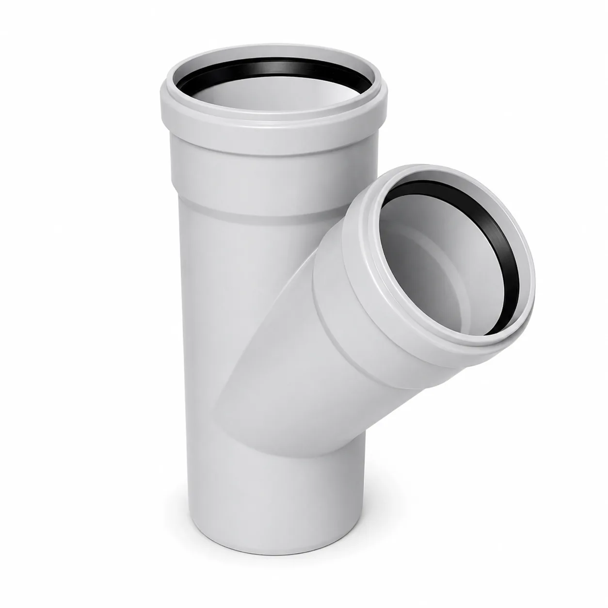
Read the DN 100 row against our 4.43 l/s. With square entries, DN 100 carries 4.0 l/s — our stack fails. With swept entries, DN 100 carries 5.2 l/s and passes with margin. The design decision is not a bigger pipe. It is a different branch fitting.
The secondary vent column comes from Table 12, which pairs each stack size with the vent size it needs — DN 100 stack with a DN 50 vent for our case. That combination reaches 7.3 l/s, an 82% gain over the square-entry primary ventilated stack of identical bore. Worth knowing before anyone proposes upsizing 24 metres of riser to DN 125.
Two footnotes travel with both tables and get dropped constantly: DN 80 is the minimum size where WCs are connected in System II, and DN 100 is the minimum where WCs are connected in systems I, III and IV. Our stack carries WCs in System I, so DN 100 was the floor regardless of what the flow calculation said.
Why the swept entry buys 30% more capacity
The tables state the difference; the UK national annex to BS EN 12056-2 explains it. Suction forms in the stack immediately below a discharging branch inlet, and the size of that suction depends on the radius or slope of the inlet. A large radius or a 45-degree entry minimises it. A near-horizontal entry with a small radius does the opposite. Branch inlets significantly smaller in diameter than the stack are less critical.
That suction is what empties trap seals by induced siphonage. The annex also notes the reverse failure: back pressure above offsets and bends can blow foul air through a trap seal, and changes of stack direction can foam detergents and create further pressure swings.
The practical warning from the same annex is worth pinning to the drawing. Sharp bends at the base of a stack cause large back pressures by restricting stack airflow, and offsets shorter than 3 m in the wet part of a stack produce large pressure fluctuations. If your architect wants the stack to jog around a structural beam halfway up, that offset is a hydraulic event, not a detailing convenience. These annex clauses are informative rather than normative — but they describe the physics the normative tables are built on.
Branch pipes: gradient, length, bends and drop
Sizing the stack is half the job. The branches feeding it carry their own limits, and venting a branch changes all of them. For an unventilated branch in System I, Table 5 sets a maximum pipe length of 4.0 m, a maximum of three 90-degree bends (the connection bend not counted), a maximum drop of 1.0 m where the pipe inclines at 45 degrees or more, and a minimum gradient of 1%. Vent that same branch and Table 8 relaxes it to 10.0 m maximum length, no limit on bends, 3.0 m maximum drop, and a minimum gradient of 0.5%.
Halving the minimum gradient from 1% to 0.5% and more than doubling the permitted run is what buys you a long branch across a flat soffit. That trade — one vent pipe against a re-planned bathroom — rarely appears in the merchant guides.
A precision point that separates a clean specification from a queried one: EN 12056-2 expresses gradient as a percentage, not as a 1:80 or 1:40 ratio. The ratio form is UK Approved Document H language. Writing “1:80 to EN 12056-2” mis-cites the standard, and it is exactly the kind of thing a reviewer flags. National regulations may impose additional or different requirements, and Annex A of the standard directs you to them — so confirm the current national rules for your market rather than assuming the EN values are the whole obligation.
The two rules that quietly kill designs
Clause 5.5 states that the nominal diameter of discharge pipes shall not be reduced in the direction of flow. No reducing a DN 110 stack to DN 100 below the last connection to save on the buried run. It reads as obvious and gets violated on real drawings every year.
Clause 5.4 sets the minimum depth of water seal at 50 mm. Note this is the EN minimum — several national codes require deeper seals for particular appliances, which is another reason to check local requirements alongside the EN calculation. In System III, Table 6 tightens it further for specific appliances: a kitchen sink on a 40 mm trap needs a 75 mm seal, while WCs, showers, baths and floor drains sit at 50 mm.
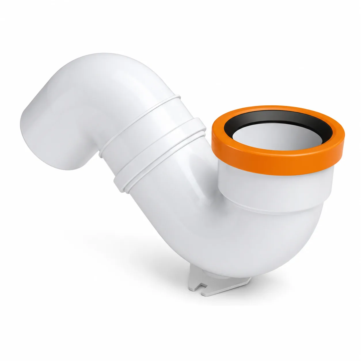
Table 6 carries one more footnote worth reading before you plan a long System III branch: where the branch length exceeds 3 m, noisy discharge may result with an increased risk of blockage. If acoustic performance matters — a hotel, a hospital, apartments with bedrooms against the riser — that is a design constraint, not a comfort preference.
DN 100 in the standard, DN 110 in the catalogue
Here is where a correct calculation meets an incorrect purchase order. EN 12056-2 sizes in DN, and Table 1 defines DN against a minimum internal diameter: DN 40 is 34 mm, DN 50 is 44 mm, DN 70 is 68 mm, DN 80 is 75 mm, DN 90 is 79 mm, DN 100 is 96 mm, DN 125 is 113 mm, DN 150 is 146 mm and DN 200 is 184 mm.
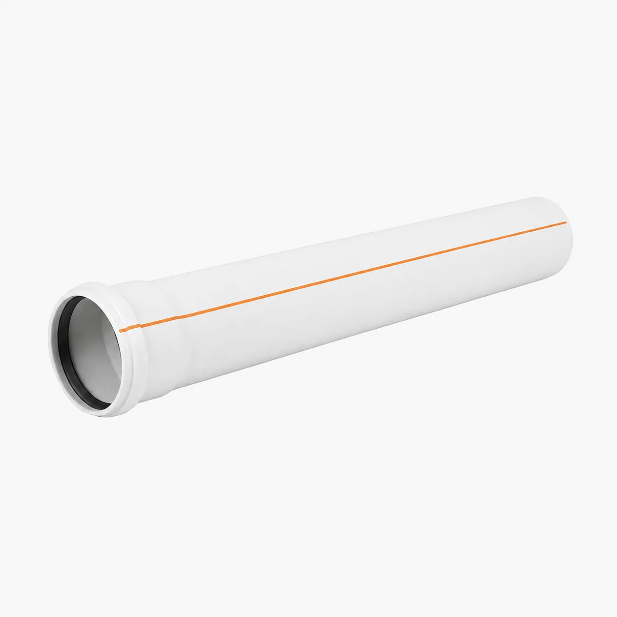
Product standards for uPVC soil pipe work in outside diameter. So a pipe sold as DN 110 satisfies the DN 100 row only if its wall leaves a bore of at least 96 mm — a wall of up to 7 mm before you fall short. The check to run on any quotation: take the outside diameter, subtract twice the quoted wall thickness, and confirm the result clears the Table 1 minimum for the DN you sized. Bekaatherm’s uPVC drainage range covers DN 50, 75, 110, 125, 160 and 200, with TYPE1 soil and waste pipe at 3.0–3.9 mm wall thickness and TYPE2 waste pipe at 1.8–3.2 mm. TYPE1 is the soil-grade wall — the one carrying WCs on a stack.
Where EN 1329 stops and EN 1401 starts
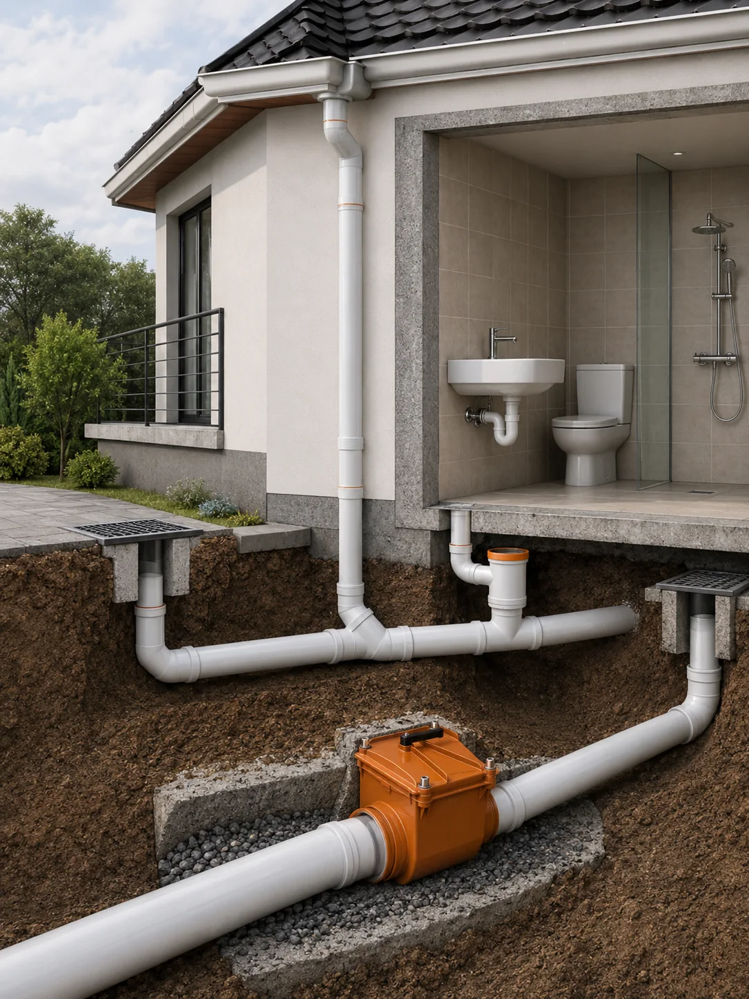
Two product standards cover the run, and the boundary is a metre from the building. EN 1329-1 covers PVC-U pipes and fittings for soil and waste discharge inside the building structure. Its application area codes are the ordering detail nobody checks: code B means above ground inside the building, or outside fixed onto the wall. Code BD means area B plus the zone under and within 1 m from the building where pipes are buried in ground, and BD applies only to components of 75 mm outside diameter and above.
So a stack that passes through the slab and runs its first metre buried needs BD-marked product. Buying B-only pipe on price and using it below the slab is the classic specification failure, and it is invisible until someone reads the marking on site.
Beyond that metre, EN 1401-1 takes over for non-pressure underground drainage and sewerage, with stiffness classes SN 2 (SDR 51), SN 4 (SDR 41), SN 8 (SDR 34) and SN 16 (SDR 27.6), sizes from DN/OD 110 mm to 1000 mm, and its own application codes: U for buried more than 1 m from the building, D for under and within 1 m of it, and UD for both. And once you are outside the building envelope entirely, you have left EN 12056 behind — drains and sewers outside the building are covered by EN 752, not EN 12056.
Both product standards changed in 2026 — check your citations
If your specification template still says “EN 1329” and “EN 1401” with no edition, it is now out of date in two places. EN 1329-1:2026 was published on 5 May 2026 and supersedes EN 1329-1:2020. Three changes matter commercially. Annealing is now required before determining the Vicat softening temperature, aligning that test with the annealing that occurs during elevated-temperature cycling. Terms and definitions were aligned with EN 14541-1. And the big one: the use of recyclates is allowed up to 100%, with sourcing guidance in Annex A, while conformity must be demonstrated with one formulation at 100% virgin material and a second at maximum recyclate content.
Read that last change carefully as a buyer. “EN 1329 compliant” no longer tells you the material is virgin. Ask which formulation was type-tested and which one your order will be produced from. The companion conformity spec CEN/TS 1329-2:2026, released in May 2026, updates the 2021 edition with clarified testing for products containing recyclates and new guidance on batch and process testing frequencies, setting a minimum matrix covering type testing, batch release testing, process verification testing and audit testing.
On the buried side, EN 1401-1:2019 was withdrawn effective 10 February 2026, having been merged into EN 1401-1:2019+A1:2023. The correct current citation is EN 1401-1:2019+A1:2023. Cheap to fix, and a reviewer will notice.
Bekaatherm’s uPVC drainage line is manufactured to EN 1329 and EN 1401, and the company holds SKZ, ISO, CE and WRAS certification. Because both product standards moved in 2026, ask any supplier — including us — to state the edition and date on the mill certificate rather than accepting a bare standard number on a datasheet.
Air admittance valves and the venting alternative
Where an open vent to atmosphere is impractical, EN 12056-2 permits air admittance valves in primary ventilated systems, secondary ventilated systems and ventilated branches. They are not a free substitution. For stack ventilation, clause 6.5.3 requires the valve to be sized with Qa not less than 8 × Qtot — on our worked example at 4.43 l/s, a valve rated for at least 35.4 l/s of airflow. Undersizing here reproduces the induced siphonage the vent was installed to prevent.
One citation detail that signals you have read the source: EN 12056-2:2000 refers to the AAV standard as the draft prEN 12380, because it had not been published when Part 2 was written. It appeared as EN 12380:2002 on 4 December 2002. For Belgian projects, Annex A records that where local regulations authorise them, only class A1 air admittance valves may be used.
Sizing a stack and need to check the bore against a real product range? If you are a specifier or contractor working to EN 12056-2 and want the dimensional data — outside diameter, wall thickness by type, and the fitting range for swept branches — send us the DN schedule and we will return the matching article numbers.
Send your DN scheduleFrom calculated diameter to a bill of materials
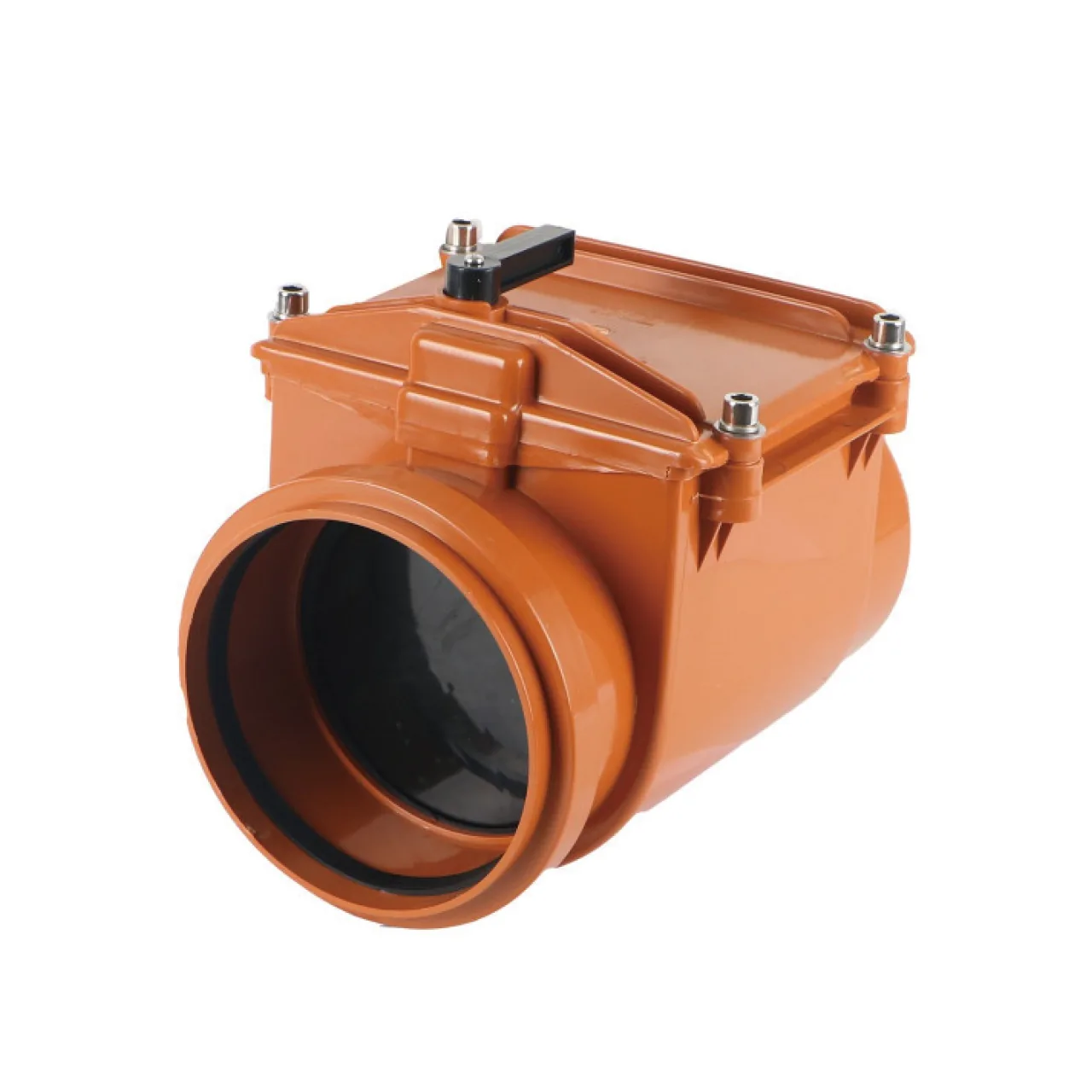
Our worked example needs DN 110 TYPE1 pipe for the stack, swept branch fittings at every floor connection, access for maintenance, and a transition to the buried system. In the uPVC pipe and fittings range that maps to single branches at 87/45 degrees in article numbers BK-319 to BK-336, 45-degree elbows BK-307 to BK-312, cleaning tees for access BK-364 to BK-367 in DN 110 to 200, and non-return valves BK-383 to BK-386 where the buried connection needs backflow protection. Double branches BK-337 to BK-349 handle back-to-back bathrooms on the same stack.
The joint itself is a rubber ring-seal push-fit socket — an elastomeric seal, no solvent cement in the drainage joint. On an eight-storey stack that matters beyond assembly speed: the ring seal accommodates thermal movement in the riser, which a rigid solvent-welded joint does not.
How we check a drainage enquiry before quoting
A drainage BOM that arrives as “DN110 pipe, 2000 m” gets four questions back before we price it, because each one changes what ships:
- TYPE1 or TYPE2? Wall thickness 3.0–3.9 mm against 1.8–3.2 mm. A soil stack carrying WCs needs the soil-grade wall, and the two are frequently confused on enquiries because the outside diameter is identical.
- Does any of it go below the slab? That determines whether you need BD-marked product for the buried metre rather than B-only, and where the EN 1401 transition sits.
- Swept or square branches? If the stack was sized on the swept-entry column of Table 11, substituting 87-degree branches on site removes the capacity the design depends on.
- Which market is it landing in? Origin is allocated per market across our Türkiye plant and a Chinese partner factory, and it is confirmed in writing on the proforma invoice per order — with certificate of origin, packing list and bill of lading consistent. If your project needs a specific origin, say so before the proforma is issued.
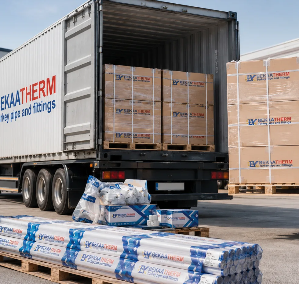
On terms, a mixed trial order is one 20GP container of pipe, fittings and valves; single-size orders run at 500 kg per size and colour. Lead time for regular in-production sizes is 15–25 days. Payment is 30% T/T deposit with 70% against copy B/L, and trade terms are FOB İstanbul or Mersin by default, with CFR and CIF on request. A 20GP gives roughly 33 m³ usable against a payload of about 28 tonnes — drainage pipe fills the volume long before it reaches the weight limit, which is why mixed loading at roughly 60% pipe, 30% fittings and 10% valves by volume is the sensible way to fill it.
The specification checklist
Everything above, compressed into what should appear on the drawing or in the spec clause:
- System type stated explicitly (I, II, III or IV), with the national requirement noted where one applies.
- ∑DU, the K value with its Table 3 justification, and the resulting Qww shown as a calculation, not just an answer.
- Stack DN with the Table 11 or Table 12 capacity it was checked against, and whether square or swept entries were assumed.
- Minimum internal diameter confirmed against Table 1 for the actual product offered — not assumed from the outside diameter.
- Branch gradients as percentages, with the ventilated or unventilated limits for length, bends and drop.
- Application area codes: B or BD above and within 1 m, U / D / UD beyond it.
- Product standard editions written out in full: EN 1329-1:2026 and EN 1401-1:2019+A1:2023.
The stack that fails inspection is rarely the one that was calculated wrong. It is the one where nobody wrote down which system was assumed, and the branch fittings that arrived on site were square-entry because they were cheaper.
For importers and project buyers pricing a drainage package. We manufacture uPVC drainage to EN 1329 and EN 1401 across DN 50 to DN 200, with SKZ, ISO, CE and WRAS certification — copies available on request. Tell us the DN schedule and destination market and we will come back with article numbers, the certificate package and a container loading plan.
Request a quotation Message us on WhatsAppFrequently Asked Questions
What size soil pipe do I need for a block of flats?
Calculate it rather than defaulting to 110 mm. Sum the discharge units for every appliance on the stack, multiply the square root by the frequency factor for the building type, then match that flow against the stack capacity table. A DN 100 stack with swept entries carries 5.2 l/s.
What is the minimum gradient for a branch discharge pipe?
In System I, an unventilated branch needs a minimum gradient of 1% and a ventilated branch 0.5%. System II requires 1.5% either way. EN 12056-2 states gradient as a percentage, not as a 1:80 style ratio.
Does DN 110 pipe satisfy a DN 100 design?
Only if the bore clears 96 mm, which is the minimum internal diameter for DN 100 in Table 1. DN in the sizing tables refers to internal diameter while product catalogues quote outside diameter, so subtract twice the wall thickness and check.
Can I reduce the pipe diameter further down the stack?
No. Clause 5.5 of EN 12056-2 states that the nominal diameter of discharge pipes shall not be reduced in the direction of flow. Sizing is set by the worst case at the base, and narrowing downstream creates the surcharge the calculation exists to prevent.
How do I size an air admittance valve for a stack?
Size it so the valve airflow Qa is at least eight times the total flow rate Qtot. For a stack designed at 4.43 l/s that means a valve rated for 35.4 l/s or more. The valve should comply with EN 12380:2002.
Is EN 12056-2:2000 still current in 2026?
Yes. It sits at CEN review-enquiry stage with a review completion date of 3 June 2026, but no superseding edition of Part 2 has been published. Cite EN 12056-2:2000 and check the CEN record before issuing a long-lead specification.
What is the difference between application codes B and BD?
Code B covers above ground inside the building or fixed to an external wall. Code BD adds the buried zone under and within 1 m of the building, and applies only to sizes of 75 mm outside diameter and above. A stack passing through the slab needs BD.