Most leaking flanges on HDPE pipe were tightened correctly. The crew followed the criss-cross pattern, hit the torque figure the engineer specified, pressure-tested the line, and went home. Two days later the joint weeps. Nobody did anything wrong in the moment — they just skipped a step that lives in a technical note almost nobody on site has read.
Polyethylene creeps. Under the clamping load of a bolted joint the flange face relaxes, bolt pre-load drops, and the seal that was perfect on Friday afternoon is a leak path by Monday. The Plastics Pipe Institute’s TN-38 handles this with a mandatory re-torque 4 to 24 hours after the initial tightening. That single instruction, plus the fact that the backing flange (not the pipe) usually sets the pressure ceiling of the assembly, explains most of the field failures people blame on bad gaskets.
Key takeaways
- A flanged HDPE joint is three parts: a stub end or flange adapter fused to the pipe, a loose backing flange (the steel ring) that slides over it, and the bolts. The ring never touches the water.
- The flange sets the rating, not the pipe. PIPA POP007 warns that catalogue PN/Class figures for flange assemblies are “nominal only”. A PN10 backing ring on PN16 SDR11 pipe gives you a PN10 system.
- The re-torque is mandatory, not optional. PPI TN-38 requires a second tightening to the initial target torque 4 to 24 hours later, to compensate for bolt creep and nut embedment.
- Tightening rounds change with bolt count. 4, 8 and 12-bolt flanges go 30% → 60% → 100% plus a rotational round. Flanges with 16+ bolts go 25% → 50% → 75% → 100%.
- Only 10–20% of applied torque becomes bolt pre-load — the rest is eaten by friction. That is why lubrication is a procedural step, not a nicety.
- Check the standard edition. EN 12201-3 was revised on 30 January 2024, superseding the 2011+A1:2012 edition most supplier pages still quote. Mating dimensions sit in ISO 9624:2019+A1:2021.
- Below 110 mm, flanges are usually the wrong tool. Compression fittings give the same demountable mechanical joint with no bolts, no gasket and no re-torque visit.
Stub end, flange adapter, backing ring: what you are actually ordering
Three words get used for two-and-a-half parts, and buyers order the wrong one constantly. The stub end or flange adapter is polyethylene. It butt-fuses to the end of your HDPE pipe and its machined face becomes the sealing surface. The backing flange — also called the backing ring or loose flange — is the separate metal ring that slips over the stub end’s collar and carries the bolts. It provides clamping force and nothing else. It never contacts the fluid, which is why it can be steel on a potable water line without a coating question about the water side.
The stub end versus flange adapter distinction is where terminology goes soft. Common usage is that a stub end is short and needs dedicated stub clamps to hold it in a fusion machine, while a flange adapter has a longer body you can clamp like ordinary pipe. Usage varies by supplier and by region, though, and ISO 9624 titles both together as “flange adapters and loose backing flanges” rather than separating them. Do not assume your supplier’s vocabulary matches your specification’s — check the drawing and the fusion length before the order ships.
One sequencing rule is genuinely universal and worth more than the terminology debate: the backing ring goes onto the pipe before you fuse the stub end. There is no way to fit it afterwards. Forget it and the fix is cutting the joint off and re-fusing, which on a 400 mm main is a half-day and a wasted fitting. Once the stub end is fused, the ring spins freely on the pipe, and that free rotation is what lets you line the bolt holes up with the valve or the mating flange.
When to flange instead of fuse — and when not to
Butt fusion produces a joint as strong as the pipe wall with no bolts, no gasket and no corrosion path. A flange is what you use when you deliberately want the joint to come apart again, or when you are meeting something that cannot be fused at all.
Best for
- Metal transitions. PE cannot be fused to ductile iron, steel or a cast valve body. A flanged joint is the standard answer.
- Anything with a service interval. Pumps, butterfly valves, flow meters, strainers, air valves. If it will be pulled for maintenance in its lifetime, do not fuse it in.
- Chamber and structure penetrations. Where the pipe enters a valve chamber or a pump house wall and the internal pipework has to be removable.
- Sectional removal. Lines that get pulled out of a trench or a pit in sections, including temporary dewatering and mine-site pipework.
- Sites with no fusion power or no certified welder. A bolted joint needs a torque wrench, not a 15 kW generator and a certified operator.
Not for
Straight buried runs. This is where specifications get padded with flanges “for future access” and the decision quietly costs money for fifty years. Every flange you bury is a bolted leak path a fused joint does not have, a steel ring corroding in wet soil, and a component that needs excavation to re-torque if it weeps. If nobody has a concrete plan to open that joint, fuse it.
There is also a beam-bending problem specific to buried flanges. PE systems are end-load bearing, and POP007 notes that flanges provide a fully end-load resistant joint — the joint transmits axial load rather than pulling apart. That is a strength, but an unsupported flange in soft bedding also carries bending stress across a rigid bolted plane. Support it properly or do not put one there.
What pressure rating does the finished joint actually have?
This is the most expensive misunderstanding in HDPE flanging, and it is worth stating flatly: the rating printed on your pipe is not the rating of your flanged joint.
PIPA POP007, verbatim: “these pressure ratings are nominal only, and advice from the flange manufacturer should be sought to clarify the actual pressure rating of the assembly.”
POP007 is explicit about why. Backing flange thicknesses differ between manufacturers and between drilling patterns, and flange thickness drives the pressure the ring can hold. The document warns that care should be taken to confirm the pressure rating of the flange actually used suits the system it goes into. Translated to the yard: bolt a PN10 backing ring onto PN16 SDR11 pipe and you have built a PN10 system. The pipe is still PN16. The line is not.
It helps to know where the pipe’s own number comes from, because it is not arbitrary. PE100 pressure classes derive from P = (20 × MRS) / [C × (SDR − 1)], where MRS is the minimum required strength — 10 MPa for PE100 — and C is the design coefficient, 1.25 for water. SDR is the ratio of outside diameter to wall thickness, so a lower SDR means a thicker wall.
| PE100 pipe class | Rated pressure (water, 20°C) | Assembly ceiling if bolted to a PN10 ring |
|---|---|---|
| SDR11 | PN16 — 16 bar | 10 bar (you lose 6 bar at the joint) |
| SDR17 | PN10 — 10 bar | 10 bar (matched) |
Two qualifiers that most catalogue pages drop. Those bar figures are rated at 20°C, on a 50-year design basis — run the line warmer and the allowable pressure falls. And the C = 1.25 coefficient is the water figure; other fluids and other national codes use different coefficients. Quote the temperature and the design basis when you specify, not the bare number, because “PN16” on its own does not tell an engineer enough to sign anything off.
Bolt torque, tightening rounds, and the re-torque nobody comes back for
The PPI TN-38 technical note is the primary document here, and it is free. If you assemble HDPE flanges and have not read it, that is the highest-value hour available to you this month.
The rounds change with bolt count
Nearly every article on this subject flattens the procedure into a generic “30, 60, 100 percent.” That is right for small flanges and wrong for large ones. TN-38 splits it:
- 4, 8 and 12-bolt flanges: Round 1 to 30% of target torque, Round 2 to 60%, Round 3 to 100%, then a rotational round.
- 16 bolts and above: Round 1 to 25%, Round 2 to 50%, Round 3 to 75%, Round 4 to 100%, then a rotational round.
- Pre-tightening: in sequence to 10–20 foot-pounds, but never exceeding 20% of the target torque.
- The rotational round: clockwise, continuing until no further bolt or nut rotation occurs at 100% of the target torque for each nut. It is not one lap — it is however many laps it takes to stop moving.
Why lubrication is step two, not a nicety
POP007, quoting TN-38, puts a number on something crews rarely think about: when you use torque control to establish pre-load, typically only about 10% to 20% of the applied torque converts to bolt tension. The rest is consumed by friction under the bolt head and the nut face. Change the friction and you change the pre-load while the torque wrench reads exactly the same. That is why TN-38’s checklist says to liberally lubricate the bolt threads, the nut threads and the flange surface under the nut — and why a torque figure calculated for lubricated bolts is meaningless on dry, rusty ones.
Reference seating torques — and their fine print
TN-38 publishes example seating torques for HDPE-to-HDPE joints. Read the qualifiers first: these assume non-plated bolts and studs with a nut factor of K = 0.16 for lightly greased hardware, an HDPE flange face seating stress of 1200 psi minimum to 1800 psi maximum, and a joint between two HDPE flange adapters without a rubber gasket.
| Nominal size | Bolts × diameter | Seating torque (ft-lbs, min–max) |
|---|---|---|
| 2 in | 4 × 0.625 in | 23 – 35 |
| 4 in | 8 × 0.625 in | 33 – 50 |
| 6 in | 8 × 0.75 in | 50 – 75 |
| 8 in | 8 × 0.75 in | 80 – 120 |
| 12 in | 12 × 0.875 in | 105 – 160 |
| 16 in | 16 × 1.000 in | 180 – 270 |
| 24 in | 20 × 1.25 in | 290 – 435 |
| Source: PPI TN-38. Values are estimates for lubricated, non-plated hardware between two HDPE flange adapters, no gasket. The engineer of record sets the actual figure. | ||
Two warnings attached to that table. TN-38 states that when bolting to ductile-iron pipe, steel flanges or butterfly valves, the flange face contact area is about half — so the correct torque for that pair is measurably less. Tightening a PE-to-valve joint to the PE-to-PE figure over-stresses the plastic face. And these are imperial values for ASME-pattern bolting. Do not convert them to newton-metres and apply them to an EN 1092-1 metric assembly: bolt counts, bolt diameters and face contact areas all differ. For metric flanges, get the table from the backing-flange manufacturer or the engineer of record.
The re-torque: the step that prevents the Monday leak
TN-38’s non-gasketed method applies the specified HDPE seating torque to the flange adapters, “followed by a mandatory re-torque applied 4-hours to 24-hours after completion of the initial torque application.” The stated purpose is to compensate for possible bolt-creep, nut embedment, and gasket compression-set where gaskets are used.
Mandatory is the operative word. Polyethylene under sustained compressive load relaxes, and the pre-load you set at 15:00 is not the pre-load you have at 09:00 the next day. Build the return visit into the programme before you price the job. Crews that treat it as optional are the ones re-excavating.
Gaskets, corrosion and support: the three long-term decisions
You may not need a gasket at all
POP007 states that gaskets may not be necessary when using PE flanges, provided sufficient compressive load can be applied and the sealing surfaces are not excessively rough or damaged. The reasoning it quotes from Headford at Stewarts and Lloyds Plastics: the viscoelastic and creep properties of polyethylene force the flange face into parallelism with its opposite number even under modest long-term bolting loads, and the PE flows into surface imperfections, sealing off potential leakage paths. The same creep that loosens your bolts is what makes the seal.
Practice is regional, and POP007 says so directly: non-gasketed joints are commonplace in the US and to a lesser extent in the UK and Europe, while historical Australian practice has been to use gaskets. So this is a specification question, not a universal rule — check what your project documents call for before you leave a gasket out. Where a gasket is used, a full-faced elastomer gasket of 1/8 inch thickness and roughly 70 Shore A durometer is a commonly cited specification. TN-38 itself declines to give gasket selection guidance and refers you to the gasket designer.
The PE never corrodes. The ring does.
Here is the failure mode nobody budgets for. Your stub end will outlive the project. The steel backing flange sitting in wet clay, coastal soil, or a chamber that floods twice a winter will not — and when the ring’s section loss gets bad enough, clamping force goes with it. Specify the ring’s protection to match the environment, not the pipe’s expected life.
POP007 lists three routes: flanges and fasteners coated to a galvanising code, stainless steel flanges and fasteners, or polymeric coatings used together with stainless steel fasteners. The standards it names (AS/NZS 4680 for galvanising, AS/NZS 4158 for coatings) are Australian and New Zealand documents, so treat them as the example rather than your obligation and map the principle onto whatever code governs your market. The principle travels: galvanised for benign dry conditions, stainless or coated-plus-stainless-fasteners for buried, submerged, coastal or chemically aggressive service. Mixing a coated ring with plain carbon steel bolts just relocates the corrosion to the bolts.
Support the joint before you bolt it
Align and support first, tighten second. Pulling two misaligned flange faces together with the bolts locks bending stress into the joint permanently, and PE will keep creeping in response to it. TN-38 separately mentions taking measures to protect PE flange joints from beam-bending strain. On a pump connection, that means the pump should not be carrying pipe weight; in a trench, it means bedding that supports the flange rather than leaving it spanning a void.
Standards, editions, and what to check on arrival
Edition numbers matter more than usual right now, because one core document changed recently and much of the published guidance online has not caught up.
| Document | What it governs | Edition to quote |
|---|---|---|
| ISO 9624 | Mating dimensions for flange adapters and loose backing flanges, dn 16–2500 mm, up to PN 25 | 2019, with Amendment A1:2021 (BS adoption published 27 Sep 2022) |
| EN 12201-3 | PE fittings for water supply and pressure drainage; clause 7.8 covers loose backing flanges and flange adapters | 2024 (published 30 Jan 2024, replacing 2011+A1:2012) |
| EN 1092-1 | Bolt-hole drilling patterns the backing ring is machined to (PN10 / PN16) | As called up by your project specification |
| PPI TN-38 | Bolt torque procedure, tightening rounds, mandatory re-torque | Guidance document, not a standard — freely published |
The ISO 9624 scope is worth knowing precisely: it covers nominal outside diameters from 16 mm to 2500 mm at nominal pressures up to PN 25, and it applies to loose backing flanges made from metal, from thermoplastics, or from a combination of the two. Cite it as 2019+A1:2021 rather than the bare 2019 edition. The published catalogue entries do not disclose what A1 changed, so confirm with the full text if the amendment is material to your design.
The EN 12201-3 revision is the one to watch. The 2024 edition replaced 2011+A1:2012 and aligned the loose backing flange and flange adapter dimensional requirements in clause 7.8 with ISO 9624:2019. The revision also brought in PE 100-RC materials with enhanced slow crack growth resistance, expanded fabricated fitting size ranges, and references mechanical fittings to ISO 17885:2021. Maximum allowable operating pressure is 25 bar at a reference temperature of 20°C. A corrigendum dated 2024 was incorporated, and the DIN adoption carries a 2025 release date — so if your contract calls up a specific edition, confirm which one before you order, since requirements vary by market and by the edition your specification names.
Incoming inspection: read the ring
When backing flanges land on site, the marking is your entire traceability chain. POP007 sets out what should be there: the standard the flange is made to, the size (DN), the rating, the material grade, the manufacturer’s name or trademark, and a heat or batch number that correlates to the material test certificate. Lettering should be no less than 3 mm on flanges under 10 mm thick, or 5 mm on thicker ones, and where the marking is indented, low-stress round-nosed stamps should be used — a sharp stamp creates a crack initiation site in a load-bearing ring.
An unmarked backing ring with no heat number is an untraceable ring. If a pressure test fails and you cannot tie the component back to a material certificate, you have no route to a claim and no way to know whether the rest of the batch shares the defect. Reject on marking before you reject on dimension — it is the faster check and it fails more often.
Below DN110: where compression fittings replace the flange
Everything above assumes you need a flange. Below 110 mm on buried water and irrigation, you often do not — and specifying one anyway is how small-diameter jobs get expensive.
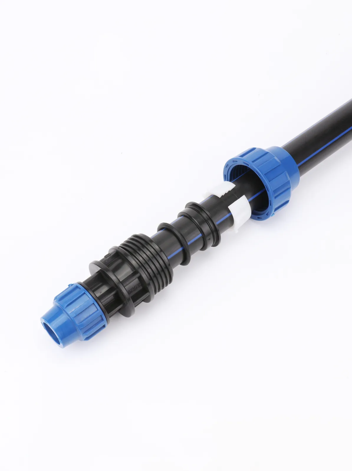
Ask what the flange is really buying you. On a 63 mm irrigation submain, the answer is usually “a joint I can take apart,” and a mechanical compression fitting meets that directly. Compression fittings clamp the pipe with a threaded nut and a grip ring: demountable, no fusion machine, no site power, no gasket procedure, no torque table, no 4-to-24-hour return visit. The flange route on the same line means two fused stub ends, two backing rings, a bolt set, a gasket decision and a corrosion-protection decision.
Where the crossover sits: flanges and stub ends dominate at DN110 and above, and at every valve, pump and metal transition regardless of diameter. Below 110 mm on distribution, service connections and irrigation, compression is normally the cheaper mechanical answer and the flange is overkill.
Where our own range sits — and where it does not
Being straight about scope: Bekatherm does not manufacture HDPE stub ends, flange adapters or backing rings. If you need flanged components for a DN400 transmission main, we are not your supplier for that item, and this guide is not a sales page for one.
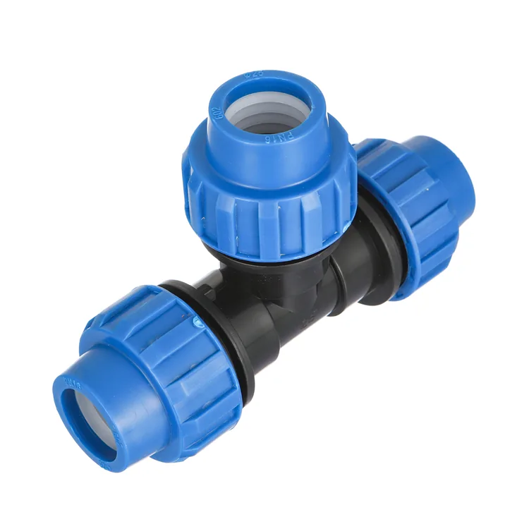
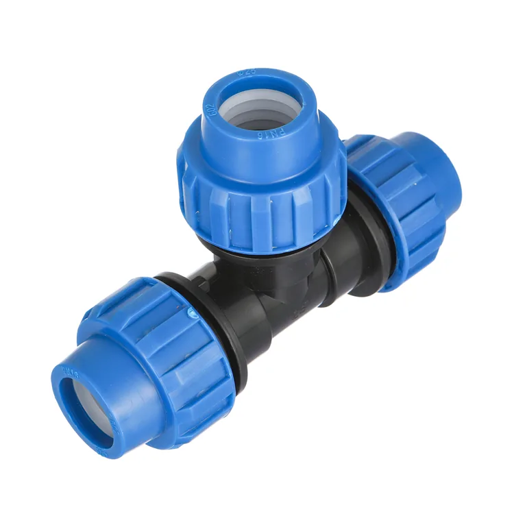
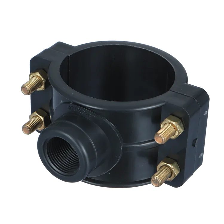
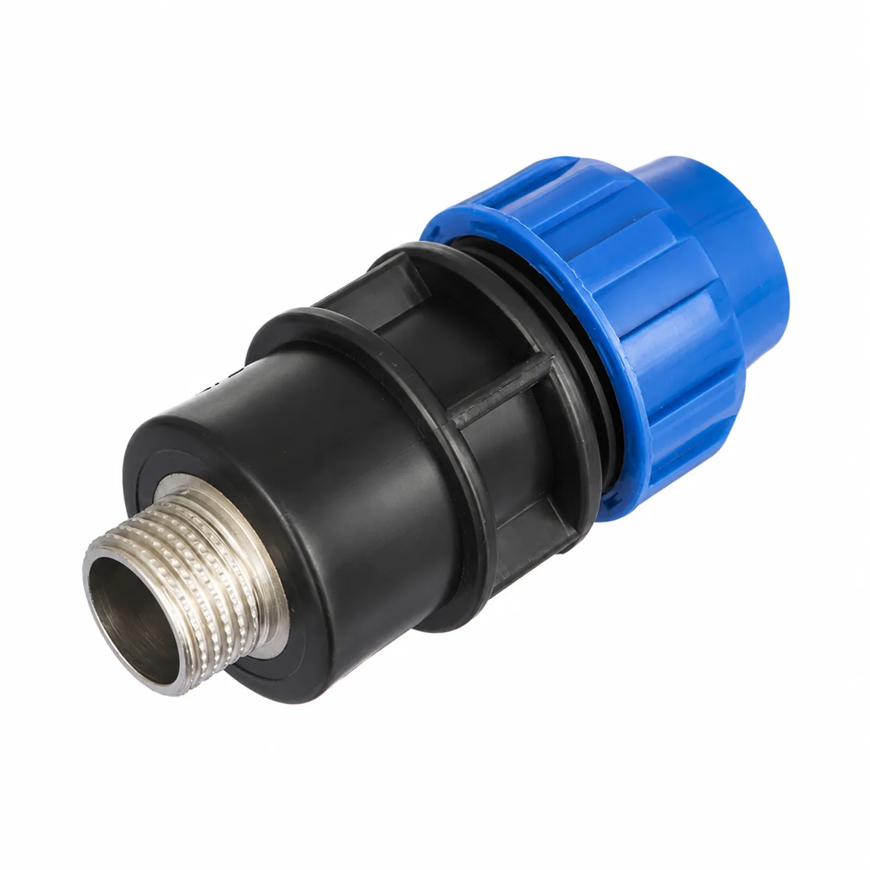
What we do make is the small-diameter mechanical alternative: PN10 polypropylene HDPE compression fittings in sockets, elbows, equal and reducing tees, caps, compression ball and female valves, and threaded transitions in BSP sizes from 1/2 inch to 4 inch. Fittings run 20–110 mm; single and double saddle clamps go up to 315 mm. The range is built against ISO 4427, EN 12201, DIN 8074 / 8075 and ISO 14236, and it is certified under SKZ (Germany), ISO, CE and WRAS — see our certifications for the current scope of each. Note that a certification covers the products in its stated scope; none of it extends to flanged components we do not produce.
How we handle an enquiry that includes flanged items
Buyers regularly send a bill of quantities that mixes compression fittings with stub ends and backing rings, because both live under “HDPE mechanical fittings” in the spec. Our process on those is fixed, and it tells you what a quotation from us will and will not contain.
- We split the BOQ by diameter and joint type first. Lines at 20–110 mm compression, plus saddle clamps to 315 mm and BSP transitions from 1/2 inch to 4 inch, are ours to quote. Flanged items are marked out of scope on the response rather than silently substituted.
- We flag substitutions instead of making them. Where a small-diameter line has been specified flanged and compression would meet the same demountable requirement, we note it against that line and leave the decision with your engineer, who owns the specification.
- Origin is confirmed in writing per order. We supply from Türkiye and from a partner plant, allocated by market. Whichever applies is stated on the proforma invoice, and the certificate of origin, packing list and bill of lading are issued to match.
- Certificates are scoped, not blanket. Ask which certification covers the exact item and size you are buying. A supplier that answers “we are certified” without naming the scope is telling you nothing — including us, if we ever do it.
On terms: a mixed trial is one 20GP mixed container of pipe, fittings and valves, single-size orders run at 500 kg per size and colour, in-production sizes ship in 15–25 days, and payment is 30% T/T deposit with 70% against copy B/L. Pricing is quoted per enquiry rather than published.
Conclusion
Flanged HDPE joints fail for boring, preventable reasons: a backing ring rated below the pipe, a torque figure borrowed from the wrong table, a re-torque nobody scheduled, and a steel ring specified for dry conditions then buried in wet clay. None of those need better components to fix. They need the assembly treated as its own engineered item with its own rating, rather than as an accessory to the pipe.
Before your next order, check two things: which edition of EN 12201-3 your specification actually calls up, and whether the flanged items below 110 mm on your drawing genuinely need to be flanged. If the answer to the second is no, you can compare the compression option against your line list and take the bolts, gaskets and return visits out of the programme entirely.
Frequently Asked Questions
What is the difference between an HDPE stub end and a flange adapter?
In common usage, a stub end is short and needs dedicated stub clamps to hold it in a fusion machine, while a flange adapter has a longer body you can clamp like ordinary pipe. Terminology varies by supplier and region, so check the drawing rather than the product name.
Why does my HDPE flange leak a day after I torqued it?
Polyethylene creeps under the clamping load, so bolt pre-load drops in the hours after assembly. PPI TN-38 requires a mandatory re-torque to the initial target torque 4 to 24 hours after the first tightening, to compensate for bolt creep and nut embedment.
Does a PN16 pipe give me a PN16 flanged joint?
Not necessarily. PIPA POP007 states that catalogue pressure ratings for flange assemblies are nominal only and that flange thickness varies between manufacturers. A PN10 backing flange on PN16 SDR11 pipe produces a PN10 assembly, so confirm the rating with the flange manufacturer.
Do I need a gasket between two PE flange faces?
Often not. POP007 says gaskets may be unnecessary on PE flanges where sufficient compressive load is applied and the faces are undamaged, because the PE flows into surface imperfections. Non-gasketed joints are common in the US, less so in Europe, so follow your project specification.
Which standard covers HDPE flange mating dimensions?
ISO 9624:2019+A1:2021 covers mating dimensions for flange adapters and loose backing flanges from dn 16 mm to 2500 mm up to PN 25. EN 12201-3:2024 clause 7.8 covers the fittings themselves and aligns its dimensional requirements with ISO 9624:2019.
Can I use compression fittings instead of flanges?
Below 110 mm on buried water and irrigation, usually yes — compression gives the same demountable mechanical joint without bolts, gaskets or a re-torque visit. At DN110 and above, and at any valve, pump or metal transition, the flanged assembly remains the correct choice.
What backing ring material should I use for a buried joint?
The PE never corrodes but the steel ring does, so match protection to the soil. POP007 lists galvanised coating, stainless steel flanges and fasteners, or polymeric coatings used with stainless fasteners. For buried, submerged or coastal service, avoid pairing a coated ring with plain carbon steel bolts.