A 10-metre run of standard PP-R pipe grows 60 mm when you heat it 40 degrees. Not 6 mm. Sixty. That is a finger’s length of pipe that has to go somewhere, and if you clamped both ends into concrete it goes sideways, into a wall, or into the shoulder of a fitting until something lets go.
Most pages that answer “how much does PPR expand” stop at the coefficient. This one carries one job all the way through: work out the movement, size the flexible leg that absorbs it, size the loop if a leg will not fit, then set the bracket spacing. Every number below comes from a published manufacturer manual, a trade-association bulletin, or the ISO standard itself. And there is a trap in the equation worth naming in the first minute rather than the last: the length you plug in is not the length of the run.
Key Takeaways
- Standard (homogeneous) PP-R expands 0.15 mm per metre per kelvin. Glass-fibre-reinforced PP-R expands 0.035 mm/m·K, roughly a quarter as much; aluminium-foil composite sits at about 0.03 mm/m·K.
- ΔL = α × L × ΔT. L is the free length between two fixed points, not the length of the run. ΔT is measured from the installation temperature, not from 20 °C.
- The flexible leg that absorbs the movement is Ls = 15 × √(d × ΔL) for PP-R. Two independent manufacturers publish the same constant of 15. The 12 you may have seen is the PEX constant from the plumbing code — do not reuse it.
- A U-loop needs a minimum width of 2 × ΔL plus a safety distance. Where there is no room, pre-stressing at installation shortens the required leg by about 29 %.
- ISO 15874 contains no support-spacing table and no expansion coefficient. It governs dimensions, pressure classes and test methods. Spacing comes from the manufacturer’s manual, and the manuals do not fully agree with each other.
- Bracket spacing tightens as the water gets hotter: a Ø50 homogeneous pipe takes 120 cm spans at 20 °C wall temperature but only 95 cm at 70 °C. Vertical runs get a 20 % allowance on the horizontal figure.
- Short runs under about 6 m with a change of direction usually self-compensate, so no special provision is needed — provided nothing blocks the elbow’s room to move.
How much PP-R actually moves, by pipe type
The coefficient of linear thermal expansion, written α, tells you how many millimetres one metre of pipe grows per kelvin of temperature rise. A kelvin and a Celsius degree are the same size, so 0.15 mm/m·K and 0.15 mm/m·°C mean the same thing. For homogeneous PP-R — plain single-layer pipe, no reinforcement — that figure is 0.15 mm/m·K, and it is stable across the industry. Wefatherm’s specification manual gives 0.150, SPK publishes 0.15, and Kalde lists 1.5 × 10⁻⁴ K−1 tested to DIN 53712 — the same number written differently.
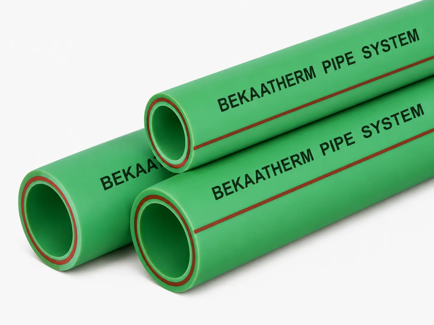
Reinforcement changes the answer dramatically. A glass-fibre middle layer resists the axial growth of the polypropylene around it, and the composite pipe lands at 0.035 mm/m·K — a factor of 4.3 lower. Aluminium-foil composite sits at roughly 0.03 mm/m·K, though only two sources publish that figure, so treat it as typical and confirm it against the pipe you are buying.
| Pipe construction | α (mm/m·K) | Growth over 10 m at ΔT 40 K | Practical consequence |
|---|---|---|---|
| Homogeneous PP-R | 0.15 | 60 mm | Needs a designed leg or loop on most hot runs |
| Glass-fibre reinforced PP-R | 0.035 | 14 mm | Often absorbed by natural direction changes |
| Aluminium-foil composite PP-R | ~0.03 | ~12 mm | Similar to fibre; foil also blocks oxygen ingress |
That table is the whole argument for reinforced pipe in exposed hot-water work. Fibre does not make expansion vanish — 14 mm still has to go somewhere — but it moves the problem from “design a loop into a ceiling void with no room for one” to “let the existing elbow take it”. On a retrofit where routing is already fixed by the old steel, that difference decides whether the job is buildable.
One honest complication. The Plastic Pipe and Fittings Association’s User Bulletin 20 lists polypropylene at 4.3 × 10⁻⁵ in/in/°F under ASTM D696, which converts to about 0.077 mm/m·K — roughly half the 0.15 PP-R pipe makers publish. Both are real. ASTM D696 measures a small free specimen of resin over a low temperature range; 0.15 is the system design value the pipe industry quotes across the service range. Design to 0.15. A leg sized for 60 mm handles 31 mm without complaint, and the reverse is not true.
Do you even need an expansion provision?
Over-engineering costs money too. The PPFA’s guidance is that runs generally under 20 feet — about 6 m — with changes in direction usually possess enough natural flexibility that no special precautions are required. Their scope covers pipe of nominal size 4 inches or less installed above ground, which fits most PP-R distribution work.
Best for skipping the detail
- Short branch runs under about 6 m with a change of direction and clear space at the elbow.
- Cold-water-only runs where installation and operating temperatures sit within a few kelvin of each other.
- Fibre or aluminium composite pipe on moderate lengths, where ΔL over 10 m at 40 K is 14 mm or less.
Not for skipping the detail
- Any straight homogeneous run over about 6 m on hot water. A 10 m run at ΔT 40 K moves 60 mm and has nowhere to put it.
- Runs where an elbow sits hard against a wall, slab or duct. The PPFA is explicit that the extra length must not be constrained by an elbow placed too closely to a wall — a change of direction with no room to swing is not one.
- Risers through floor slabs, where each penetration is a potential unplanned anchor.
- Anything buried in screed or chased into a wall, where the failure is invisible until it is a leak.
One instinct to resist: fitting a metal bellows into a plastic line. Plastic pipe under thermal load deflects laterally rather than compressing a joint along its axis, so the bellows never sees the movement it was designed for while the pipe bows somewhere it should not. Geometry — a leg or a loop — has no seals and no service interval.
The two inputs almost everyone gets wrong
The equation is simple: ΔL = α × L × ΔT — change in length in mm, coefficient in mm/m·K, free pipe length in metres, temperature difference in kelvin. Wefatherm, Kalde and the PPFA bulletin all publish the same form. The arithmetic is not where jobs go wrong. The two inputs are.
Trap one: L is the free length, not the run length
Free pipe length means the length between two points at which the pipe is secured in a fixed manner. Sliding brackets do not count — they hold the pipe up and guide it but let it travel, so a pipe passing through six sliding clips is still one continuous free length.
This cuts both ways. Plug in the full 40 m of a distribution main and you get a terrifying 240 mm, over-engineering a loop that was never needed because fixed points at each branch tee already divided that main into 6 m sections. The opposite error is worse: assume fixed points where there are only sliding clips, fit a short leg, then discover on commissioning that the real free length was three times the assumption. Mark every genuine fixed point before calculating anything.
Trap two: ΔT starts at the installation temperature
ΔT is the difference between the assembly temperature and the operating temperature — not the difference from 20 °C, and not the difference from the design ambient. Pipe installed in an unheated shell in February at 5 °C and later run at 70 °C sees ΔT = 65 K, not 50 K. That is 30 % more movement than the assumed figure, and it is the single most common reason a correctly-calculated leg turns out to be short.
A corollary almost nobody writes down: fix your fixed points at low ambient temperatures where you can. Clamping cold means the pipe spends its working life in compression as it warms, and polypropylene handles compression far more comfortably than being stretched between two anchors it cannot reach.
Chilled water is the mirror image. A run installed at 30 °C and operated at 6 °C contracts by α × L × 24, and contraction pulls fittings apart rather than pushing them together. The leg still has to be there. It just flexes the other way.
Worked example: a 14-metre plantroom run, end to end
One job carried the whole way. A Ø63 heating flow main, homogeneous PP-R, runs 14 m along a plantroom wall from a header to a riser shaft, with a fixed point at each end — so the free length is the full 14 m. The shell is unheated during first fix and the pipe is welded at about 15 °C. Design flow temperature is 70 °C.
Step 1 — the movement. ΔT = 70 − 15 = 55 K. So ΔL = 0.15 × 14 × 55 = 115.5 mm. The pipe will try to become 11.5 cm longer than the wall it is fixed to. That number is why the corner detail matters more than the pipe spec.
Step 2 — the flexible leg. The pipe turns 90 degrees into the shaft, so the vertical section after that elbow is the leg that has to bend. Ls = 15 × √(63 × 115.5) = 1,280 mm. The first bracket on the riser side must sit at least 1.28 m above the elbow, and everything in between must be free to move — no clips, no penetration collars, no cable tray hard against the pipe.
Step 3 — what if 1.28 m does not exist. Say the shaft entry sits 900 mm below a slab. Two options, and they land on the same number. Pre-stress the leg at installation: Lsv = 15 × √(63 × 115.5/2) = 905 mm. Or add a fixed point at the midpoint so each 7 m section moves 57.75 mm, needing Ls = 15 × √(63 × 57.75) = 905 mm. Both fit, with nothing to spare.
Step 4 — bracket spacing along the 14 m. At a Ø63 pipe running 70 °C wall temperature, the published span is 105 cm. Fourteen metres takes 14 spans, so 13 intermediate brackets between the two fixed points, all of them sliding type with soft inserts.
Step 5 — the alternative that changes the answer. Specify fibre-reinforced pipe and ΔL drops to 0.035 × 14 × 55 = 26.95 mm, so Ls = 15 × √(63 × 26.95) = 618 mm. The 900 mm shaft entry absorbs that with 280 mm of margin and no pre-stressing, and bracket spacing relaxes too. The reinforced pipe costs more per metre and removes an entire detail from the drawing, along with the risk that a second-fix trade clips the leg.
Both roads to 905 mm in Step 3 rely on the same physics: the leg length scales with the square root of the movement, so halving ΔL only shortens the leg by 29 %.
Sizing the expansion leg, the loop, and the pre-stressed leg
Three formulas cover almost every situation you will meet on a PP-R job. All three use the same material constant K = 15, which Wefatherm and Kalde publish independently of each other — a rare piece of agreement in a market where every manual has its own conventions.
| Detail | Formula | Published worked example |
|---|---|---|
| Bending leg (flexible arm) at a change of direction | Ls = 15 × √(d × ΔL) | d 40 mm, ΔL 60 mm → 735 mm |
| Pre-stressed bending leg (fitted under tension) | Lsv = 15 × √(d × ΔL/2) | d 40 mm, ΔL 60 mm → 520 mm |
| U-loop minimum width | Amin = 2 × ΔL + safety distance | ΔL 60 mm, SA 150 mm → 270 mm |
Why the constant is 15 and why a PEX calculator will lie to you
The 15 is not a rule of thumb someone rounded off. The PPFA derives the leg length as L = [1.5 E/S]½ × [D × ΔL]½, where E is the modulus of elasticity and S the allowable stress; since E = S/ε, the first bracket collapses to a constant set by the material’s allowable strain. PP-R’s flexural modulus of 800 N/mm² at 23 °C is low compared with metal, which is exactly why a plastic leg absorbs 115 mm by bending rather than thrusting into an anchor.
Change the material and the constant changes with it. The Hawaii Plumbing Code’s expansion-arm provision uses the identical formula shape, LB = C × √(D × ΔL), with C = 12 for PEX. Plug PP-R numbers into a PEX calculator and you get a leg 20 % short with no warning, because the formula runs happily either way. Confirm which constant a calculator applies before trusting its output.
Pre-stressing: the option nobody explains
Pre-stressing means installing the leg deliberately displaced, so the pipe starts life pulled toward one end of its travel and uses the full width of the gap rather than half. The payoff is real: 520 mm instead of 735 mm on the published example, a 29 % saving. In a riser shaft where you are fighting for every centimetre between a slab and a branch tee, that is often the difference between a compliant detail and an improvised one.
The catch is that it depends on the installer doing it, in the right direction, and a pre-stressed leg is invisible once the shaft is boarded. Mark it on the drawing with the displacement direction and check it before the boards go on. There is no way to verify it afterwards without opening the shaft.
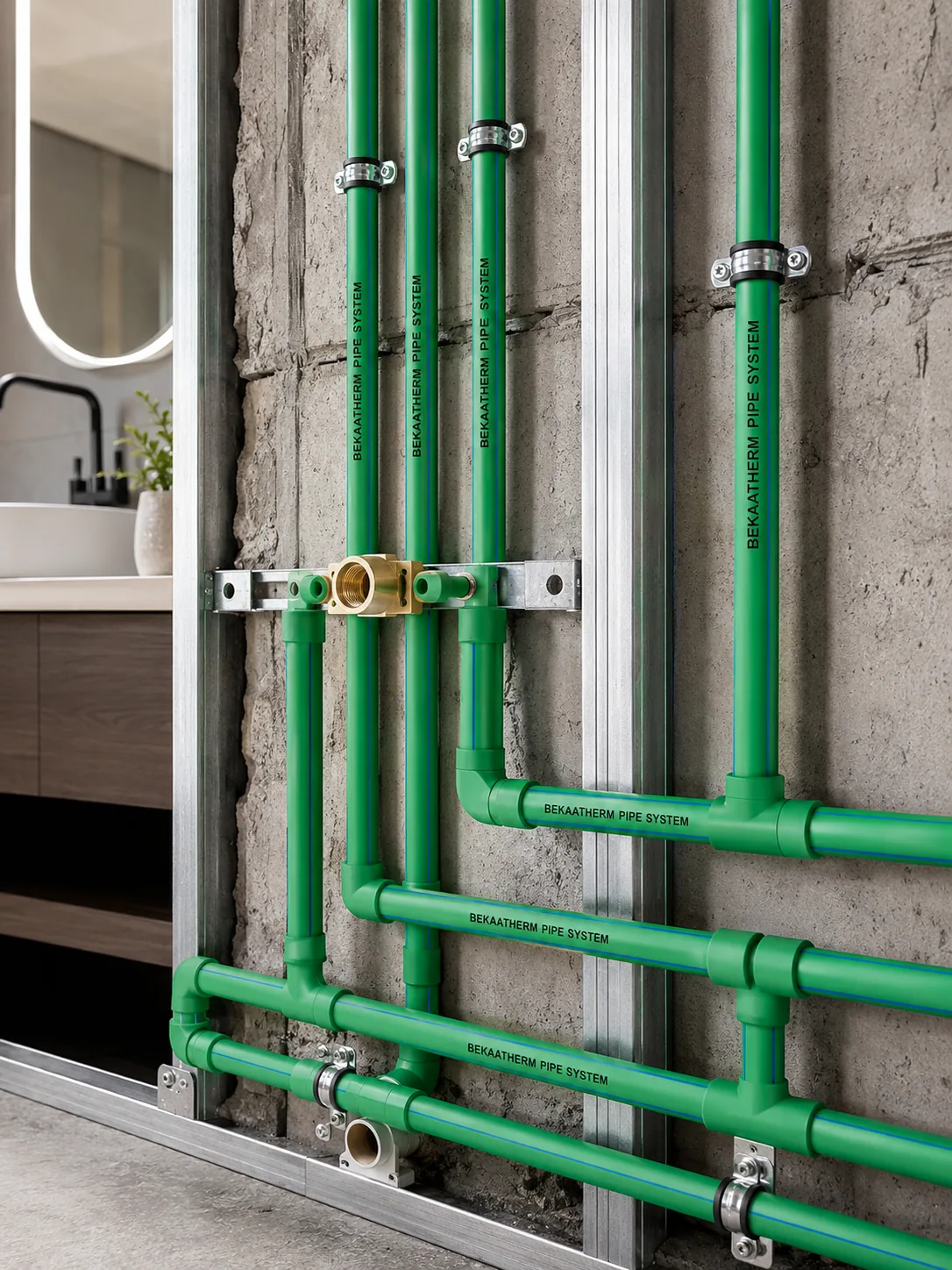
Support spacing tables, and why two suppliers disagree
Support spacing is a separate problem from expansion, and worth keeping apart in your head. Expansion legs stop the pipe destroying itself lengthways; bracket spacing stops it sagging under its own weight plus the water, which gets worse as the pipe warms and softens. The table below is homogeneous PP-R on horizontal runs, in centimetres, indexed by pipe wall temperature.
| OD (mm) | 20 °C | 40 °C | 60 °C | 70 °C |
|---|---|---|---|---|
| 20 | 60 | 60 | 55 | 50 |
| 25 | 75 | 70 | 65 | 60 |
| 32 | 90 | 80 | 75 | 70 |
| 40 | 100 | 90 | 85 | 80 |
| 50 | 120 | 110 | 100 | 95 |
| 63 | 140 | 130 | 115 | 105 |
| 75 | 150 | 140 | 125 | 105 |
| 90 | 160 | 150 | 140 | 125 |
| 110 | 180 | 170 | 160 | 140 |
| 125 | 190 | 180 | 170 | 150 |
Read down a column and spans grow with diameter, because a fatter pipe is a stiffer beam. Read across a row and they shrink with temperature, because polypropylene softens as it warms and a span that was fine cold will visibly sag hot. A Ø63 line drops from 140 cm to 105 cm between cold and 70 °C — a quarter more brackets, a real material and labour line worth pricing rather than discovering.
Vertical runs get a 20 % allowance. Take the horizontal figure for the relevant diameter and temperature and multiply by 1.2, because a vertical pipe is carrying its weight along its axis rather than bending across a span. That Ø63 line at 70 °C goes from 105 cm horizontal to 126 cm vertical.
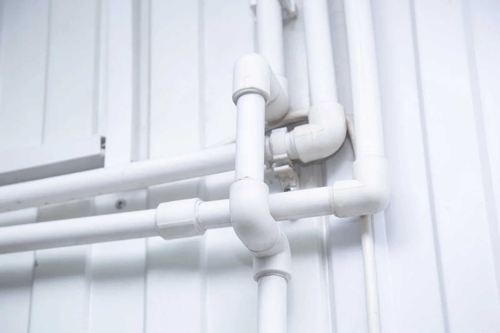
Fibre pipe spacing: use your supplier’s table, not a generic one
Reinforced pipe carries longer spans, but here the published sources genuinely disagree. Wefatherm’s fibre table gives Ø50 at 175 cm for a 20 °C wall temperature; Kalde’s equivalent gives 140 cm. That 25 % spread on the same nominal product is not a typo — it reflects different reinforcement constructions and safety factors. For homogeneous pipe the two agree within one 5 cm step, which is why the table above can be published as a single set of numbers. For fibre pipe, use the table from the manufacturer whose pipe is arriving on site. If the submittal has no such table, that absence is itself worth a question.
The reading error that costs you a whole column
Put two suppliers’ spacing tables side by side and you will find they are indexed differently. Wefatherm’s columns are headed pipe wall temperature TR in °C — an absolute figure. Kalde’s are headed temperature ΔT in K — a difference. A buyer comparing a 70 °C column against a ΔT 70 K column is comparing 70 °C water against roughly 90 °C water, and will wrongly conclude that one supplier’s pipe is far stiffer than the other’s.
Check the column heading before the numbers. If it says °C it is an absolute wall temperature; if it says K or ΔT it is a rise above ambient, and you add the ambient back before comparing. This one detail resolves most “why do these datasheets contradict each other” questions on PP-R submittals.
Fixed points versus sliding brackets: where each one goes
A fixed point does not move and defines the boundary of a free length. A sliding point holds the pipe up and guides it while permitting axial movement. Both are usually the same physical clip — what makes one a fixed point is how it is tightened and where it sits.
Which brings up something easy to do by accident: two sliding clips either side of a fitting act as a fixed point. The fitting’s larger diameter cannot pass through either clip, so the pipe is trapped between them even though each clip was meant to slide. An installer who clips neatly on both sides of every coupling has anchored the run at every coupling, and the free lengths on the drawing no longer describe the pipe on the wall.
Where fixed points are not optional
- Branch points at wall penetrations: where a branching pipe passes through a wall it must be mounted in a fixed manner. Otherwise the main’s axial movement is transmitted into the branch and the branch can be sheared off — inside the wall, where you find out about it later and expensively.
- Either side of a designed loop: a loop only works if the movement is driven into it. Without anchors bounding the section, the pipe travels somewhere else instead.
- At equipment connections: anchor before the connection so a boiler, pump or valve flange never carries the axial thrust of the run.
- To break long free lengths deliberately: as in Step 3 of the worked example, adding a fixed point is often cheaper than finding room for a longer leg.
Clip detail, which is where the drawing meets the site
Plastic pipe clips need rubber inserts. They stop the clip damaging the pipe surface at the contact point and provide the guiding and holding the pipe needs. A bare metal saddle tightened onto PP-R scores the wall and converts your sliding guide into an unplanned fixed point through friction.
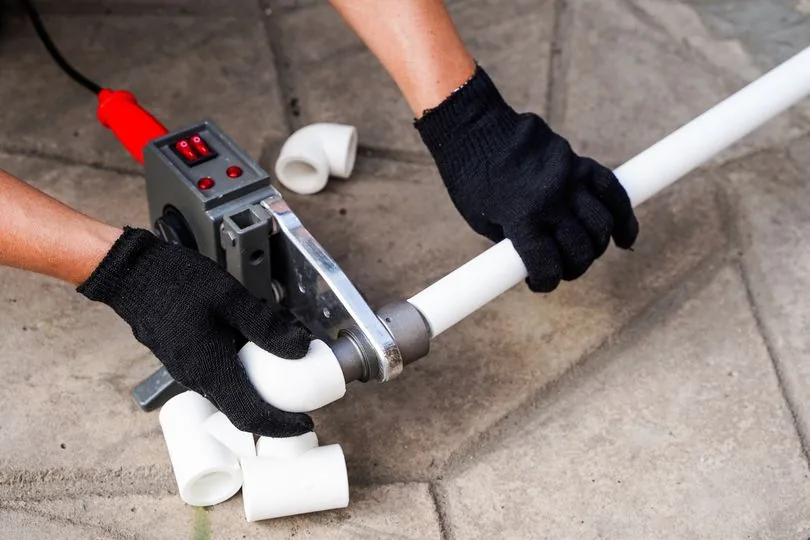
Ignore any clip torque figure quoted online — none of the manufacturer manuals or standards checked publishes one. The executable check is better anyway: the clip must hold the pipe without deforming the wall, and after final tightening a sliding clip must still move axially by hand. If you cannot slide it, it is a fixed point, whatever the drawing calls it. Same failure family: a socket-fusion fitting welded too close to a bracket becomes a fixed point exactly where you did not want one, so keep the weld and the clip apart — our guide to socket fusion welding for PP-R covers the cooling times by diameter.
Working out whether homogeneous or reinforced pipe suits your layout?
For contractors and specifiers at the routing stage: send us the diameters, the operating temperature and the tightest space you have to fit a leg into, and we will run the ΔL and leg lengths against both pipe types so you can see which one removes a detail from the drawing.
Send us the layout Message us on WhatsAppWhat ISO 15874 does and does not cover
Several pages on this topic imply that support spacing comes from ISO 15874. It does not. ISO 15874-2:2013 specifies the requirements for pipes made from polypropylene for hot and cold water installations within buildings, and for heating systems, under operating pressures and temperatures appropriate to the class of application. Dimensions, pressure classes, material requirements, test methods. There is no support-spacing table in it and no thermal expansion coefficient.
That is not a gap in the standard. Spacing and expansion detailing depend on the specific pipe construction, so they live in the manufacturer’s manual by design. The consequence for a specifier is direct: writing “supports to ISO 15874” means nothing, because there is nothing there to comply with. Name the manufacturer’s installation manual and its revision instead.
What it does give you is the application-class framework, which is how you pick the right temperature column. ISO 15874-1 sets out the classes, each evaluated over a 50-year design life.
| Class | Typical field of application | Spacing column to read |
|---|---|---|
| Class 1 | Hot water supply, 60 °C | 60 °C |
| Class 2 | Hot water supply, 70 °C | 70 °C |
| Class 4 | Underfloor and low-temperature radiators, to 60 °C | 60 °C |
| Class 5 | High-temperature radiators, to 80 °C | Interpolate below 70 °C; ask the maker |
Class 5 is worth flagging. It runs to 80 °C but the published spacing tables stop at 70 °C, so there is no column to read. Do not extrapolate the trend yourself — ask the manufacturer for the 80 °C figures in writing. If they cannot produce them, the pipe was not characterised for the duty you are about to put it to. Maximum operating pressures also shift by class and pipe series, so read them off the series and SDR you are actually buying.
The 50-year figure quoted everywhere has a specific meaning behind it. ISO 15874-2:2013 Table A.2 gives PP-R a design stress of 6.93 MPa at 20 °C over 50 years, dropping by class — 3.02 MPa for Class 1, 2.12 for Class 2, 3.29 for Class 4, 1.89 for Class 5. That is why a pipe rated for Class 5 carries a lower working pressure than the same pipe on cold water.
What it looks like when this is done wrong
Thermal expansion failures have a signature, and it is not usually a burst pipe. It is a fitting that has been worked back and forth by a run that had nowhere to go.
- Sheared branch at a wall penetration. The main expands, the branch was never fixed at the wall, and it takes the whole axial load at its weakest cross-section.
- Snaking between clips. Straight when cold, visibly wavy when hot — too few brackets for the wall temperature, or brackets that grip when they should slide.
- Crushed or scored pipe at a clamp. Over-tightened clips without soft inserts. The score becomes a stress concentration on a pipe cycled thermally several times a day.
- Movement at an appliance connection. No anchor between run and equipment, so a boiler or pump flange absorbs thrust it was never sized for.
- The delayed one. Everything passes the commissioning pressure test, because a cold test loads the pipe radially and expansion loads it axially. A pressure test tells you nothing about expansion detailing. The heating season does.
How we check this before pipe leaves the factory
To be straightforward about where we sit: Bekaatherm manufactures PP-R piping across a 120,000 m² plant with 1000+ staff and 10,000 moulds, running 98 items across 4 systems and exporting to 118+ countries over 30 years. Pipe is produced to the ISO 15874 family, with dimensions to DIN 8077 and general quality requirements to DIN 8078, certified through SKZ in Germany, CE, and WRAS. Products carry a 50-year warranty against material and manufacturing defects, matched to the 50-year design life at rated pressure and 20 °C under ISO 15874.
None of that designs your bracket layout. What it means is that the pipe’s outside diameter and wall thickness match the dimensional standard your spacing table assumes — the quiet precondition every one of those spans depends on. On a tight retrofit the calculation above sometimes moves the answer from homogeneous PP-R pipe to fibreglass-reinforced pipe, which is a different price per metre and a different drawing. Our comparison of fibreglass versus aluminium composite PP-R covers the trade-offs beyond expansion alone.
Need the pipe and the sizes to match the layout you just calculated
For importers and project contractors ready to specify: our minimum order is 500 kg per size and colour, lead time on regular running sizes is 15–25 days, payment is 30 % T/T deposit with 70 % against copy B/L, and trade terms are FOB İstanbul or Mersin by default with CFR and CIF on request. Tell us the diameter schedule and destination and we will price it.
Request a quotation See the price list pageConclusion
Four numbers carry this whole topic: 0.15 mm/m·K for plain PP-R, 0.035 for fibre, a leg constant of 15, and a loop width of twice the movement plus clearance. Get the two inputs right — free length between fixed points, and ΔT from the temperature at which you actually welded the pipe — and the rest is a square root. Get them wrong and the arithmetic is flawless and the answer is useless.
Take the longest hot run on your current drawing and calculate its ΔL before anything else. If the number surprises you, you have found the detail worth spending an hour on. From there it is worth checking your diameter schedule against a PP-R pipe sizes chart, since the spacing table and the leg formula both key off the outside diameter you end up buying.
Frequently Asked Questions
How much does PPR pipe expand when heated?
Standard homogeneous PP-R expands 0.15 mm for every metre of pipe per kelvin of temperature rise. A 10 m free length heated 40 K grows 60 mm. Glass-fibre-reinforced PP-R expands 0.035 mm/m·K, so the same run grows only 14 mm.
How do I calculate the expansion of a PPR run?
Use ΔL = α × L × ΔT. L is the free length in metres between two fixed points, not the total run length, and ΔT is the difference between the temperature at which you installed the pipe and the operating temperature. Both errors are common and both produce a leg that is too short.
How far apart should PPR pipe clips be?
It depends on diameter and pipe wall temperature. For homogeneous PP-R on horizontal runs, Ø25 takes 75 cm at 20 °C and 60 cm at 70 °C, while Ø63 takes 140 cm at 20 °C and 105 cm at 70 °C. Increase the relevant horizontal span by 20 % for vertical runs.
How long does an expansion leg need to be for PPR?
Ls = 15 × √(d × ΔL), with d the outside diameter in mm and ΔL the calculated movement in mm. A Ø40 pipe moving 60 mm needs a 735 mm flexible leg. Pre-stressing the leg at installation shortens it to 520 mm using Lsv = 15 × √(d × ΔL/2).
Does ISO 15874 specify support spacing for PPR pipe?
No. ISO 15874-2:2013 covers dimensions, pressure classes, material requirements and test methods for PP pipes in hot and cold water and heating installations. It contains no support-spacing table and no thermal expansion coefficient — those come from the manufacturer’s installation manual.
Can I use a PEX expansion loop calculator for PPR pipe?
No. The formula shape is the same but the material constant differs — plumbing code guidance uses C = 12 for PEX, while PP-R manufacturers publish K = 15. Using the PEX constant gives a leg about 20 % shorter than PP-R needs, with nothing in the output to flag the error.
Do short PPR runs need an expansion loop?
Usually not. Runs under roughly 6 m with a change of direction generally have enough natural flexibility that no special provision is needed, per PPFA guidance for pipe of 4 inches nominal size or less above ground. The condition is that the elbow has room to move — a bend hard against a wall does not count.
Why do two suppliers’ PPR spacing tables give different numbers?
Often because they are indexed differently: one column heading is absolute pipe wall temperature in °C, the other is a temperature rise ΔT in K. Check the heading before comparing values. Fibre-reinforced tables also genuinely differ between makers by up to 25 %, so use the table from the manufacturer supplying your pipe.