Under the US model plumbing code, a horizontal PVC pipe clamp goes every 4 ft (1.22 m), and a vertical one every 10 ft. That is the number most crews are looking for, so there it is in the first line. It is also the number that gets people in trouble, because it is a legal minimum for one material at one temperature — not a design.
Here is the part the distributor blogs leave out. The same model table puts polypropylene under 1 in at 2 ft 8 in (813 mm) horizontal — tighter than PVC, not looser. So a crew that finishes a UPVC waste stack on Monday and starts a PP-R hot-water run on Tuesday, reusing Monday’s 4 ft spacing, under-supports the hot line by about a third. This page carries both tables, shows which rule wins when the manufacturer sheet and the local code disagree, and works the expansion arithmetic through so you can actually place an anchor.
Key Takeaways
- PVC, horizontal: 4 ft (1.22 m) maximum between supports; 10 ft vertical, per the IPC/UPC model hanger tables.
- Polypropylene under 1 in: 2 ft 8 in (813 mm) horizontal, 4 ft vertical. Small-bore PP-R needs closer supports than PVC.
- Temperature governs, not just diameter: manufacturer data for Schedule 40 PVC drops 1 in pipe from 5.5 ft at 60 °F to 2.5 ft at 140 °F.
- Never clamp tight. A guide must let the pipe slide axially; only a designated anchor grips. The UPC also bars hangers placed on the coupling.
- Expansion math: ΔL = L × α × ΔT. A 10 m plain PP-R run at ΔT 50 K grows 75 mm. In glassfibre PP-R (α 0.035) the same run grows 17.5 mm.
- EN drainage practice: BS EN 12056-2 advises supports no more than 3 m apart, with a bracket within 300 mm of the joint.
- Local codes override: Chicago requires PVC risers clamped every 4 ft — 2.5× tighter than the model code’s 10 ft.
The PVC pipe clamp spacing table
The values below come from the hanger spacing table in the US model I-Codes — the IPC and UPC families that most US jurisdictions adopt with amendments. They are legal minimums. Your pipe supplier’s own engineering sheet may be stricter, and if it is, the stricter number is the one you install to.
| Material and size | Horizontal max | Vertical max |
|---|---|---|
| PVC, all sizes | 4 ft (1.22 m) | 10 ft (3.05 m) |
| ABS, all sizes | 4 ft (1.22 m) | 10 ft (3.05 m) |
| CPVC, 1 in and smaller | 3 ft (0.91 m) | 5 ft (1.52 m) |
| CPVC, 1-1/4 in and larger | 4 ft (1.22 m) | 10 ft (3.05 m) |
| Polypropylene, smaller than 1 in | 2 ft 8 in (813 mm) | 4 ft (1.22 m) |
| Polypropylene, 1-1/4 in and larger | 4 ft (1.22 m) | 10 ft (3.05 m) |
| PEX, 1 in and smaller | 2 ft 8 in (813 mm) | 4 ft (1.22 m) |
| Copper tubing | 6 ft (1.83 m) | 10 ft (3.05 m) |
| Copper pipe | 12 ft (3.66 m) | 10 ft (3.05 m) |
Read the copper row against the PP row and the whole logic of the table appears. Copper holds 12 ft horizontally because it is stiff and barely moves. Small-bore plastic gets 2 ft 8 in because it is not stiff and it moves a lot. The table is not really about material names — it is about stiffness and thermal movement, which is why the same material changes rows at a diameter threshold.
The rules around the spacing number
Three requirements sit alongside the interval and get missed far more often than the interval itself:
- Support next to every joint. The UPC calls for a support adjacent to the joint, not exceeding 18 in. A fitting is a concentrated mass on a flexible line, and an unsupported one hangs off the pipe rather than the other way round.
- Never put the hanger on the coupling. The UPC states plainly that hangers shall not be placed on the coupling. Resting a clip on the coupling shoulder is a common jobsite habit — it looks tidy, it feels secure, and it point-loads the one part of the assembly you least want stressed.
- Guide the riser mid-span. For sizes 2 in and smaller, a guide must be installed midway between required vertical supports to prevent perpendicular pipe movement. On a 10 ft vertical allowance that means a guide at 5 ft, so a compliant riser has roughly twice as many touch points as the headline number suggests.
- Brace against sway. Long horizontal runs need bracing at intervals not exceeding 40 ft to prevent horizontal movement — a separate requirement from vertical load support.
That third bullet is worth a second read. Ask most installers how far apart the clamps go on a small riser and they will say 10 ft. Ask how many mid-story guides that riser needs and the room goes quiet.
One more thing about the vertical column, because it is the most misread part of the table. A vertical support is not carrying bending load — the pipe is not sagging under its own weight when it stands on end. It is carrying the accumulated dead weight of everything above it, plus the water inside. That is why the vertical numbers are generous compared with horizontal ones, and also why the guide requirement exists separately: the vertical clamp stops the stack sinking, and the guide stops it bowing sideways. Two different jobs, two different fixings, and swapping one for the other satisfies neither.
Why hot water halves your spacing
The code table gives one number per material. Manufacturer engineering data does something more useful: it derates spacing as the contents get hotter, because plastic loses stiffness with temperature. Published support spacing for Schedule 40 PVC, in feet, runs like this:
| Size | 60 °F | 100 °F | 140 °F |
|---|---|---|---|
| 1/2 in | 4.5 ft | 4 ft | 2.5 ft |
| 1 in | 5.5 ft | 4.5 ft | 2.5 ft |
| 2 in | 6 ft | 5 ft | 3 ft |
| 4 in | 7.5 ft | 6.5 ft | 4 ft |
The mechanism is worth understanding rather than memorising. Thermoplastics do not have a fixed stiffness the way steel effectively does across normal service temperatures — the modulus falls as the material warms, so the same pipe carrying the same water weight deflects further between the same two supports simply because it is hotter. The support table is really a deflection table in disguise. That also explains why the derating is steeper at small diameters: a 1/2 in pipe has very little section to begin with, so it has less stiffness to lose before sag becomes visible.
A 1 in line goes from 5.5 ft to 2.5 ft — spacing more than halves across that temperature band. Notice something else: at 60 °F the manufacturer allows 5.5 ft where the code caps you at 4 ft, so the code is stricter. At 140 °F the manufacturer wants 2.5 ft where the code still says 4 ft, so now the manufacturer is stricter. Neither source is reliably the tighter one. You have to check both every time.
There is also a hard stop. The same engineering guidance says consideration should be given to the use of CPVC or continuous support above 120 °F. Read that as what it is: past roughly 120 °F, PVC has stopped being a support problem and become a material selection problem. No clamp layout rescues a pipe running outside its temperature band, which is the point at which most specifiers move to CPVC or PP-R pipe for the hot leg.
PP-R is not PVC: the row installers miss
If you searched for PVC clamp spacing but the job in front of you is a hot-water system, this is the section that matters. The two materials move at different rates, and the gap is not marginal.
| Material | Expansion coefficient α | Growth of a 10 m run at ΔT 50 K |
|---|---|---|
| UPVC (PVC-U) | 0.075–0.100 mm/m·K | 37.5–50 mm |
| Plain PP-R | 0.15 mm/m·K | 75 mm |
| Glassfibre-reinforced PP-R | 0.035 mm/m·K | 17.5 mm |
| Aluminium-foil PP-R | 0.030 mm/m·K | 15 mm |
Plain PP-R moves roughly 1.5 to 2 times as much as UPVC for the same temperature rise. That is the physical reason the model code drops small-bore polypropylene to 2 ft 8 in while leaving PVC at 4 ft. Reuse a PVC spacing plan on a PP-R hot line and you have both under-supported it and given it more room to snake between the clips.
Where composite pipe changes the layout
The reinforced grades are the interesting row. A glassfibre core cuts α from 0.15 to 0.035 — a factor of more than four. In layout terms that is the difference between planning expansion loops into a long horizontal run and not needing them at all. A 20 m plain PP-R distribution main at ΔT 50 K grows 150 mm and has to absorb it somewhere; the same run in fiberglass PP-R pipe grows 35 mm, which a well-placed guide layout can usually take without a dedicated loop.
Aluminium-foil composite is marginally tighter again at 0.030 mm/m·K, and it adds an oxygen barrier that matters on closed heating circuits. The trade-off is that aluminium-composite PP-R needs the foil layer peeled back before fusion, which adds a step per joint. On a ceiling-void run with hundreds of joints, that step is a real cost. If the driver is purely expansion control, glassfibre gets you 88% of the benefit with no peeling; if you need the oxygen barrier, the peeling is not optional. We go through that choice in more depth in our comparison of fiberglass and aluminium composite PP-R.
Composite pipe buys you fewer expansion loops, not wider clamp spacing. The support interval still comes from the code and the manufacturer sheet.
That distinction gets muddled on site constantly. Lower α means the pipe travels less, so you need fewer places for it to travel to. It does not mean the pipe got stiffer between supports — sag is a beam problem, not an expansion problem, and the two are governed separately.
Why we only publish a metric PP-R table with a named source
You will find metric PP-R spacing tables all over the web — DN20 cold at 600 mm, DN20 hot at 300 mm, and so on. We checked several while researching this page. None cited a standard, and they contradicted each other on the same diameter: one source gave DN20 cold as 600 mm, another 650 mm; one gave DN20 hot as 300 mm, another 500 mm. Publishing a fourth version of an unsourced table would just add noise.
So take the metric interval from your pipe supplier’s own technical sheet for the exact resin and wall series you are installing, then check it against your local code and install to whichever is tighter. The code-backed values in the table above — 813 mm for small-bore PP, 1219 mm for 1-1/4 in and larger — are traceable, and they work as a sanity check on any supplier table you are handed. If a sheet tells you 1,500 mm on 20 mm hot pipe, something is wrong with the sheet.
How far apart should PP-R clamps be, in metric?
For 20–25 mm PP-R carrying water at 20 °C, published manufacturer data puts horizontal supports at about 0.95–1.0 m, tightening to 0.70–0.85 m at 80 °C. Vertical runs may go 1.3 times wider. Take the final figure from the sheet for the pipe you are actually installing.
The table below is the exception to the rule stated above, and it is included because it has a name on it: the Wavin Pilsa PPR Product and Technical Manual, page 22, for S 3.2 (SDR 7.4) polypropylene pipe. Pilsa is a Turkish PPR producer working to EN ISO 15874, so its resin and wall series are directly comparable with other Türkiye-made PP-R. The values are for horizontal runs; the manual multiplies them by 1.3 for vertical pipe, and the last column applies that at 60 °C, the temperature most hot-water risers actually see.
| Pipe OD (mm) | Horizontal, 20 °C (cm) | Horizontal, 60 °C (cm) | Horizontal, 80 °C (cm) | Vertical, 60 °C (× 1.3, cm) |
|---|---|---|---|---|
| 20 | 95 | 80 | 70 | ≈ 105 |
| 25 | 100 | 90 | 85 | ≈ 115 |
| 32 | 120 | 100 | 90 | ≈ 130 |
| 40 | 130 | 115 | 100 | ≈ 150 |
| 50 | 150 | 125 | 110 | ≈ 160 |
| 63 | 170 | 145 | 125 | ≈ 190 |
| Source: Wavin Pilsa, PPR Product and Technical Manual, support-spacing table for Pilsa PPR S 3.2, horizontal installation, p. 22; vertical factor 1.3 from the same page, applied and rounded here. Manufacturer recommendation, not a standard. Values for other resins, S 2.5 walls or composite pipe differ. | ||||
Read the 20 mm row against the US model-code figure quoted at the top of this page. The code says 813 mm for polypropylene under 1 in; the manufacturer sheet says 950 mm cold and 700 mm at 80 °C. Cold, the code is tighter; hot, the sheet is. That is the same crossover the Schedule 40 PVC data showed, and it is why neither source can be installed to on its own.
Riser versus horizontal run: why the multiplier exists
A horizontal PP-R pipe is a beam loaded by its own weight plus the water inside it, and the span limit is a deflection limit: the sheet is telling you how far the pipe can go before it sags visibly, and at 80 °C the material has lost enough stiffness that the span shortens by roughly a quarter. A riser carries no bending load at all. Its clamps do two other jobs: carry the accumulated dead weight down to an anchor at each floor, and stop the column bowing sideways as it expands. The 1.3 factor is the manufacturer’s allowance for the first of those; the mid-storey guide requirement covered earlier on this page handles the second. Put the anchor at the slab, the guides between, and let the per-storey growth run upward into an offset. The loop and arm sizing that absorbs it is worked in PPR thermal expansion: support spacing and expansion loops.
Which document gives what
Specifiers regularly ask for a clamp spacing “to DIN 8077” or “to EN 1329”. Neither contains one. The product standards fix what the pipe is; the installation documents and the manufacturer fix how it is supported.
| Document (current edition) | Gives a spacing? | What it does give |
|---|---|---|
| DIN 8077:2008-09 / DIN 8078:2008-09 | No | PP pipe dimensions; general quality requirements and tests |
| ISO 15874-2:2013 + A1:2018 + A2:2022 | No | Pipe series, wall, hydrostatic and impact requirements |
| EN 1329-1:2020 / EN 1401-1:2019 | No | PVC-U soil-and-waste and underground drainage product requirements |
| EN 12056-2:2000 | Yes, drainage | Supports not more than 3 m apart on sanitary pipework (see above) |
| Manufacturer technical sheet | Yes, pressure pipe | Spacing by OD and temperature for that resin and wall; the warranty assumes it |
| Source: scope clauses of the standards named; DIN editions per DIN Media catalogue. Which EN drainage standard your run needs is covered in EN 1329 vs EN 1401. | ||
So the honest answer to “what is the PP-R clamp spacing to DIN 8077” is that DIN 8077 sizes the pipe and says nothing about clamps. Ask instead for the supplier’s spacing table for the S series you are buying, check it against the sourced figures above, and install to the tighter of that table and your local code.
Anchors, guides and how tight is too tight
Every clamp on a plastic line is doing one of two jobs, and installing the wrong one is the most expensive small mistake on this page. Published guidance for plastic systems puts it bluntly: do not clamp supports tightly, because that restricts the axial movement of the pipe. Supports must carry the weight without compressing or distorting the pipe.
- Guide (sliding clamp): holds the pipe in line, carries its weight, and lets it slide lengthways. This is most of your clamps. Correctly fitted, you can push the pipe through it by hand.
- Anchor (fixed point): grips the pipe so it cannot move at all, deliberately splitting a run into two sections that each expand toward the flexible feature between them. You place these; you do not create them by accident.
Accidental anchors are the real problem. Over-tighten three consecutive guides and you have built a fixed section with nowhere to go, so the growth turns into compressive load on the fittings. A pipe penetrating a wall in mortar is an anchor whether you intended it or not. So is a clip screwed down hard onto a coupling shoulder — which is exactly why the UPC bars hangers on couplings.
The failure mode is not usually a burst. It is a joint held under permanent compressive stress for years, with the clamp edge acting as a stress raiser at the point of highest load. Impact and notch resistance are live enough concerns in this material family that ISO 15874-1 carries a 2022 amendment specifically covering the impact test. A point-loaded clamp is a manufactured notch.
There is a quick check that costs nothing on site. Once a run is clipped and before anything is boxed in, walk it and push each pipe lengthways by hand. Everything you designed as a guide should shift slightly. Anything that will not move is an anchor, and you should be able to point at the drawing and say why it is there. Crews who do this on the first floor of a job usually find two or three unintended anchors and recalibrate how hard they are driving the screws for the remaining floors. Crews who do not, find them later with a moisture meter.
Best for / not for
A tight anchor is right for: the midpoint of a run you want to expand symmetrically into loops at both ends; immediately above a floor-level support on a riser, so each storey carries its own weight; either side of a branch you need to keep dimensionally stable.
A tight anchor is wrong for: anything within a short distance of a fusion joint, where residual weld stress is already present; any position where you cannot state which direction the resulting expansion will travel; and — most commonly — every clip on a run, which is what happens when a crew is told simply to “make it secure”.
If you need to size a flexible arm to absorb the movement, the standard form is LB = C × √(D × ΔL), where D is the nominal outside diameter and ΔL the calculated expansion. The material constant C is the catch: published values differ between manufacturers and resins, and we have not found an authoritative single value for PP-R. Take C from the technical sheet for the pipe you are actually installing. Any page that gives you one number for all plastics is guessing.
Worked example: a 24 m riser, start to finish
Take a hot-water riser in an eight-storey residential block. 25 mm plain PP-R, 3 m floor-to-floor, 24 m total. Cold-fill in winter at about 10 °C, design flow at 60 °C. Here is the whole calculation.
Step 1 — how far the pipe travels
ΔT is 60 minus 10, so 50 K. For plain PP-R, α is 0.15 mm/m·K. Applying ΔL = L × α × ΔT to the full riser: 24 × 0.15 × 50 = 180 mm. The riser grows the better part of a fifth of a metre between a winter shutdown and a summer afternoon. Per storey it is 3 × 0.15 × 50 = 22.5 mm.
Try that as a thought experiment before you accept it. If the base of the riser is anchored solid and no allowance is made anywhere up the stack, 180 mm of growth has to be absorbed by the pipe going into compression — and PP-R at 60 °C is not stiff enough to take that without deflecting sideways somewhere.
Step 2 — support intervals
25 mm is under 1 in nominal, so the code row is polypropylene smaller than 1 in: 4 ft (1.22 m) vertical. Over 3 m of storey height that is a support at floor level and one at roughly 1.2 m and 2.4 m. Because the pipe is 2 in and smaller, the mid-span guide requirement applies between required vertical supports as well. In practice the crew installs a bracket at each floor plus intermediate guides at no more than 1.22 m, which for a 3 m storey means three touch points per floor.
Step 3 — decide which one is the anchor
One anchor per storey, at the floor slab. Everything else on that storey is a guide. That converts the problem from one 180 mm movement into eight independent 22.5 mm movements, each absorbed within its own floor height, with each storey carrying its own weight instead of dumping it on the base of the stack. Tighten the anchors progressively as the stack goes up, not all at the end — the same logic EN drainage practice applies to soil stacks.
Step 4 — check the fittings and the material
22.5 mm per storey still needs somewhere to go: an offset, a proprietary expansion feature, or a branch arm long enough to flex. Size it with LB = C × √(D × ΔL), taking C from the pipe manufacturer’s sheet. And check the branch PP-R fittings at each floor take-off, because that is where the residual movement lands. If the same riser were specified in glassfibre PP-R, α drops to 0.035 and the per-storey figure falls to 3 × 0.035 × 50 = 5.25 mm — small enough that an ordinary branch arm absorbs it and the expansion feature disappears from the drawing entirely.
That last comparison is usually where the material decision gets made. 22.5 mm per floor across eight floors is eight expansion details to design, install and inspect. 5.25 mm is none. Pipe selection and PN class are worth settling before the support drawings are issued, not after.
EN practice for soil and waste stacks
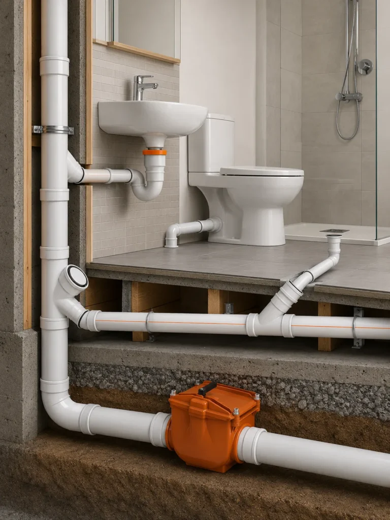
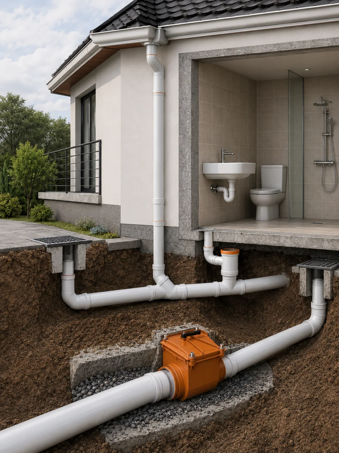
Everything above is pressure pipework. Gravity drainage plays by different numbers, and if you are working to European rather than US practice this is your table. BS EN 12056-2, the code of practice for sanitary pipework, advises that the distance between pipe supports should not exceed 3 m.
In bracket terms that resolves neatly, because soil pipe ships in 3 m lengths. Standard EN-market practice is two brackets per 3 m length: the first a maximum of 300 mm from the joint, the second at roughly the centre of the length, about 1.5 m from the first. Note how much tighter the joint rule is than the US 18 in (457 mm) figure.
- Vertical stacks: a load-bearing bracket at each floor level, carrying the weight of the pipe and its contents. One bracket per pipe length is adequate provided it sits within 600 mm of the joint.
- Build-up sequence: tighten brackets as the stack is built up, so each floor height is self-supporting and undue pressure is not imposed on the base of the stack. Get this wrong and the bottom of an eight-storey stack carries eight storeys of pipe and water.
- Stand-off from the wall face: 32 mm for 50 mm and 70 mm pipe; 38 mm for 100 mm, 150 mm and 200 mm pipe. Too close and you cannot get a fusion tool or a socket in later.
The stand-off dimension is the one that gets value-engineered out and then costs money. A bracket that holds the pipe 20 mm off the wall looks identical to one holding it at 38 mm until someone needs to cut into the stack for an added branch and there is no room to swing a tool behind the pipe. On refurbishment work, where the stack will certainly be modified again within its life, the stand-off is worth treating as a hard dimension rather than a preference.
Those figures apply to the UPVC drainage line and to PP drainage systems, both of which are made to EN 1329 and EN 1401 rather than the pressure standards. Do not carry the 3 m drainage figure back onto a pressure line — different standard, different loading, different answer.
Which rule wins when sources disagree
You now have three numbers for the same pipe: a model code value, a local code value, and a manufacturer value. Requirements vary by jurisdiction, building type and system, so treat this as the ordering logic rather than a legal ruling, and confirm the current adopted code with your local authority having jurisdiction.
- 1. The adopted local code sets the floor. It is what an inspector signs off against, and it is frequently amended from the model text.
- 2. The manufacturer sheet wins whenever it is tighter. Warranty terms typically assume installation per the manufacturer’s instructions, so beating the code but ignoring the sheet can leave you compliant and uncovered at the same time.
- 3. The project specification wins if it is tighter than both. Consulting engineers routinely tighten spacing on exposed plant-room runs for reasons of appearance and vibration that no code addresses.
Local amendment is not a hypothetical. The Chicago Plumbing Code puts PVC at 4 ft maximum horizontal and 4 ft maximum vertical, against the model code’s 10 ft vertical — a riser clamped 2.5 times more often than a generic table would tell you. The same code sets cast iron at 5 ft horizontal, rising to 10 ft where 10-foot lengths are installed, and requires swing sections or traverse joints on all vertical piping lines in buildings over 150 ft (45.75 m) tall.
One city, one table, and every number in it differs from the model. Any page that hands you a single spacing chart and implies it applies everywhere has skipped the most important step. Check what your jurisdiction actually adopted, and check the edition — the current US model edition is the 2024 IPC, with the next on a three-year cycle. Any source citing a “2026 IPC” is citing something that does not exist.
What bad clamping actually looks like
Support faults rarely announce themselves at commissioning. They surface over the first few heating seasons, usually in this order.
- Visible sag between clips. The cosmetic warning. On a hot line it also creates low points that trap air and change the flow noise.
- Ticking and knocking behind the wall. The classic symptom of a guide gripping too hard: the pipe builds up load, then releases in a stick-slip jerk. Residents report it as a knock at the moment hot water is drawn.
- Snaking on exposed runs. Expansion with nowhere to go pushes the run sideways between supports. Once visible, the pipe has already been cycling under bending stress for a while.
- Weeping at a fitting shoulder. The expensive one. A joint held in permanent compression by an accidental anchor, in a wall, discovered by a stain on someone’s ceiling.
Note the sequence there. The cheap symptoms show up first and get ignored because they are cosmetic or merely annoying, and the expensive one arrives last with no warning of its own. A residual knock in a riser two winters after handover is not a snagging item to be argued about — it is the system telling you a guide is gripping, and it is the cheapest moment you will ever get to fix it.
Worth being clear about what this costs on the supply side. A 50-year warranty against material and manufacturing defects, matched to the 50-year design life at rated pressure and 20 °C under ISO 15874-1, is a statement about the pipe. It assumes the pipe was installed supported and free to move as designed. Restrain a line so it cannot expand and you have taken it outside the conditions the design life was calculated under — no manufacturer’s warranty in this product category covers that, ours included.
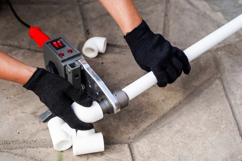
Which is why support layout deserves the same attention as the joint itself. A correct fusion weld is stronger than the pipe wall, and our heat fusion welding guide covers getting it right — but a perfect weld inside a badly clamped run still fails, just later and at the fitting shoulder rather than the seam.
How we check a pipe before it ships
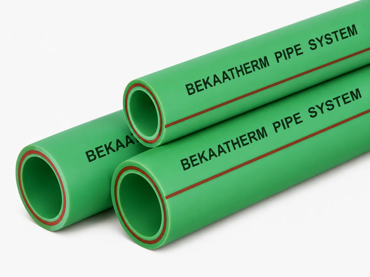
Support behaviour on site depends on the pipe being dimensionally what the drawing says. Bekatherm produces to DIN 8077:2008-09 for dimensions and DIN 8078:2008-09 for general quality requirements, with the system tested for fitness for purpose under ISO 15874-5. Production is audited by SKZ in Germany, and the potable-water range carries WRAS approval alongside CE marking. On the standards side, ISO 15874-5:2013 was last reviewed and confirmed in 2023 and remains current, carrying one amendment from 2018, with a revision under development.
The practical relevance to clamping is ovality and wall consistency. A pipe that is out of round does not sit properly in a guide — it either grips at two points or floats loose, and both defeat the layout you designed. Batch consistency across a 24 m riser matters more than the headline pressure rating, which is why the quality control process checks dimension batch by batch rather than lot by lot.
Conclusion
Clamp spacing is three decisions, not one: how far apart, which clamps grip and which release, and where the movement goes. The 4 ft PVC figure answers the first and says nothing about the other two, which is why crews who know the number still produce risers that knock. Run the expansion arithmetic for the actual material and temperature, place your anchors deliberately, and check your local amendment before you trust any published chart.
If a hot-water job is on your desk now, work out ΔL for the longest run first — it usually tells you whether the material choice is settled or still open. You can size the pipe itself against our PP-R pipe sizes chart once the layout logic is clear.
Frequently Asked Questions
How far apart should PVC pipe clamps be?
Under the US model plumbing code, PVC needs a support every 4 ft (1.22 m) horizontally and every 10 ft vertically, at all sizes. Manufacturer data tightens this for hot service, and local codes may be stricter still.
Is PP-R clamp spacing the same as PVC?
No, and it is tighter, not looser. The model code puts polypropylene under 1 in at 2 ft 8 in (813 mm) horizontally against PVC’s 4 ft, because PP-R expands roughly 1.5 to 2 times as much as UPVC for the same temperature rise.
How tight should a pipe clamp be?
Guides should not be tightened onto the pipe, because that restricts axial movement. A correctly fitted guide carries the weight and holds alignment while still letting the pipe slide lengthways through it.
Can I put a pipe clamp on the coupling?
No. The UPC states that hangers shall not be placed on the coupling. Position the support adjacent to the joint instead, within 18 in under US practice or within 300 mm of the joint in EN drainage practice.
How do I calculate how much a pipe will expand?
Use ΔL = L × α × ΔT, with length in metres, α in mm/m·K and the temperature change in kelvin. A 10 m plain PP-R run at α 0.15 and ΔT 50 K grows 75 mm; the same run in glassfibre PP-R at α 0.035 grows 17.5 mm.
Does hot water change the required support spacing?
Yes, sharply. Published data for Schedule 40 PVC drops 1 in pipe from 5.5 ft at 60 °F to 2.5 ft at 140 °F. Above 120 °F the guidance is to consider CPVC or continuous support rather than wider-spaced clamps.
What does BS EN 12056-2 require for soil pipe supports?
It advises that supports should not exceed 3 m apart. Common practice is two brackets per 3 m length, the first within 300 mm of the joint and the second near the centre, with a load-bearing bracket at each floor level on vertical stacks.