Every installer knows the rule as folklore: test it before you close the wall. It is not folklore. It is a numbered clause in a European standard, and it reads like this:
“Pipe joints shall be clad, plastered over or otherwise covered only after having been pressure tested (see 6.1), unless national regulations require accessibility of certain joints, then compliance with those national regulations shall be achieved.”
— BS EN 806-4:2010, clause 3.2.5
That single sentence sets the order of work for the whole job. It also carries a carve-out that most guides skip, and that carve-out is the reason a UK site and a Turkish site do not close a wall the same way. This page covers the depth you are legally allowed to cut, the clause that forces the test, and the honest answer to whether PPR can be buried in cement.
Key Takeaways
- In a wall 115 mm thick or less, the horizontal chase depth allowed without structural calculation is zero. EN 1996-1-1 §8.6.3 permits no horizontal chase at all in a standard 100 mm leaf.
- Vertical chases cut after construction are capped at 30 mm deep across every wall thickness band from 85 mm to over 300 mm. Only the permitted width grows with the wall.
- UK Approved Document A 2C30 gives the field version of the same idea: vertical no deeper than 1/3 of the leaf, horizontal no deeper than 1/6.
- EN 806-4 does not want pipe troweled into mortar. Unless it can be readily removed, pipework must sit in a sleeve, duct or chase, be free to expand, and carry no external load.
- UK water regulators go further than the material does: concealed pipework should not be embedded or come into contact with plaster or cement. PP-R itself tolerates burial — this is a jurisdiction question, not a material one.
- Clip spacing is not one number. On hot water at 20–25 mm OD, supports go in at roughly 600 mm against 850 mm for the same pipe on cold.
- Where expansion is deliberately prevented, the maximum distance between anchor points is 6 m.
Step 1 — How deep may you actually cut?
Most installation guides cover cutting, fusing and testing in detail and say nothing about depth. That gap matters, because the man with the wall chaser is modifying a structural element. Eurocode 6 — EN 1996-1-1, the European masonry design standard — publishes the limits in two tables. Here is the vertical one, for chases cut after the wall is built, giving sizes allowed without a structural calculation.
| Wall thickness | Max depth, chase cut after construction | Max width |
|---|---|---|
| 85–115 mm | 30 mm | 100 mm |
| 116–175 mm | 30 mm | 125 mm |
| 176–225 mm | 30 mm | 150 mm |
| 226–300 mm | 30 mm | 175 mm |
| over 300 mm | 30 mm | 200 mm |
Read the middle column again. The depth never moves. A 400 mm wall buys a wider chase, not a deeper one — depth is what removes load-bearing section, and 30 mm is where the standard stops trusting you to cut without doing sums. Most 20 mm and 25 mm PPR sits inside that. A 32 mm pipe with a clip behind it does not, and that is the size where installers quietly cut deeper and say nothing.
Forming the chase during construction buys far more room, because the mason leaves a recess instead of removing cured material: for an 85–115 mm wall the rule becomes a minimum 70 mm of wall remaining with up to 300 mm width, and 175 mm remaining at 226–300 mm thickness. Planning risers before the blockwork goes up is the cheapest decision on this list.
Now the horizontal table — the finding that should change how you price a job.
| Wall thickness | Max depth, unlimited length | Max depth, length ≤ 1250 mm |
|---|---|---|
| 85–115 mm | 0 mm | 0 mm |
| 116–175 mm | 0 mm | 15 mm |
| 176–225 mm | 10 mm | 20 mm |
| 226–300 mm | 15 mm | 25 mm |
| over 300 mm | 20 mm | 30 mm |
A standard 100 mm leaf permits a horizontal chase depth of zero. Not a shallow one. Zero, at any length, without a structural calculation. Every horizontal run cut across a thin partition on a domestic job is either engineered or non-compliant, and almost nobody engineers it.
Why so harsh? A vertical chase removes material along the line the load already travels. A horizontal one cuts across it, severing the path and leaving a hinge. A horizontal slot does far more structural damage per millimetre than a vertical one.
The practical consequence: run drops, not crossings. Bring the pipe down a vertical chase from a ceiling void or up from a floor screed, and take it horizontally in the floor build-up, in a duct, or in a stud partition — never across a thin masonry leaf. Where a horizontal move in masonry is unavoidable, EN 1996-1-1 §8.6.3(1) requires it to sit within one eighth of the wall’s clear height, above or below a floor, with eccentricity in the region of the chase kept under t/3. Outside that, vertical load, shear and flexural resistance have to be checked by calculation.
UK readers get a shorter version of the same physics. Approved Document A clause 2C30: vertical chases no deeper than 1/3 of the wall thickness (or of the leaf, in a cavity wall), horizontal chases no deeper than 1/6 of the leaf. On a 100 mm leaf that is about 33 mm vertical and about 16 mm horizontal. Two working rules travel with it — never cut a chase diagonally between start and finish, and never place chases back to back on opposite faces of the same wall.
The measurement everyone gets wrong
EN 1996-1-1 §8.6.2 NOTE 1 states that the maximum depth “should include the depth of any hole reached when forming the recess or chase.” Cut a 30 mm chase and break into a hollow block void, and your depth is not 30 mm — it is 30 mm plus the void. This is exactly how a compliant-looking chase in hollow blockwork becomes a non-compliant one, and it is why Approved Document A adds its warning about stability “particularly where hollow blocks are used.”
Step 2 — Where you may not cut at all
Depth is one constraint. Position is another, with three separate sources.
Structural exclusions come first. EN 1996-1-1 §8.6.1 is written as a principle, meaning it is not negotiable: chases shall not impair the stability of the wall. They must not pass through lintels or other structural items built into the wall, and are not permitted in reinforced masonry unless the designer specifically allowed for them. In a cavity wall each leaf counts separately — a 100 mm inner leaf is a 100 mm wall for chasing, whatever the overall construction measures.
Spacing comes second. Vertical chases need at least 225 mm of horizontal distance from an adjacent chase, recess or opening, and their cumulative width should not exceed 0.13 times the wall length. Horizontal chases must end at least 500 mm from an opening. On a short pier between a door and a window, those two rules alone can rule out concealment entirely. One relaxation is worth knowing: a vertical chase that does not extend more than one third of the storey height above floor level may go to 80 mm deep and 120 mm wide — but only in a wall 225 mm thick or more. That is what makes a low-level chase for a WC or basin feed workable in solid walls, and it does nothing for a 100 mm partition.
Third, and most often forgotten: the electrician got there first. Under BS 7671, cables concealed in walls run in prescribed zones — including a 150 mm band where wall meets ceiling and a 150 mm band either side of an internal or external corner running floor to ceiling, plus the zones directly above, below and beside an accessory. A cable buried shallower than 50 mm must either sit in one of those zones with 30 mA RCD protection or satisfy Regulation 522.6.204 another way.
That 150 mm strip beside a corner is exactly where an installer instinctively drops a feed to a basin. Cutting there does not just risk hitting a cable — it puts a hot water pipe where the next trade reasonably expects cable and nothing else. Agree drop lines with the electrician before either of you starts cutting. The zone rules quoted are UK wiring regulations; the coordination problem is universal.
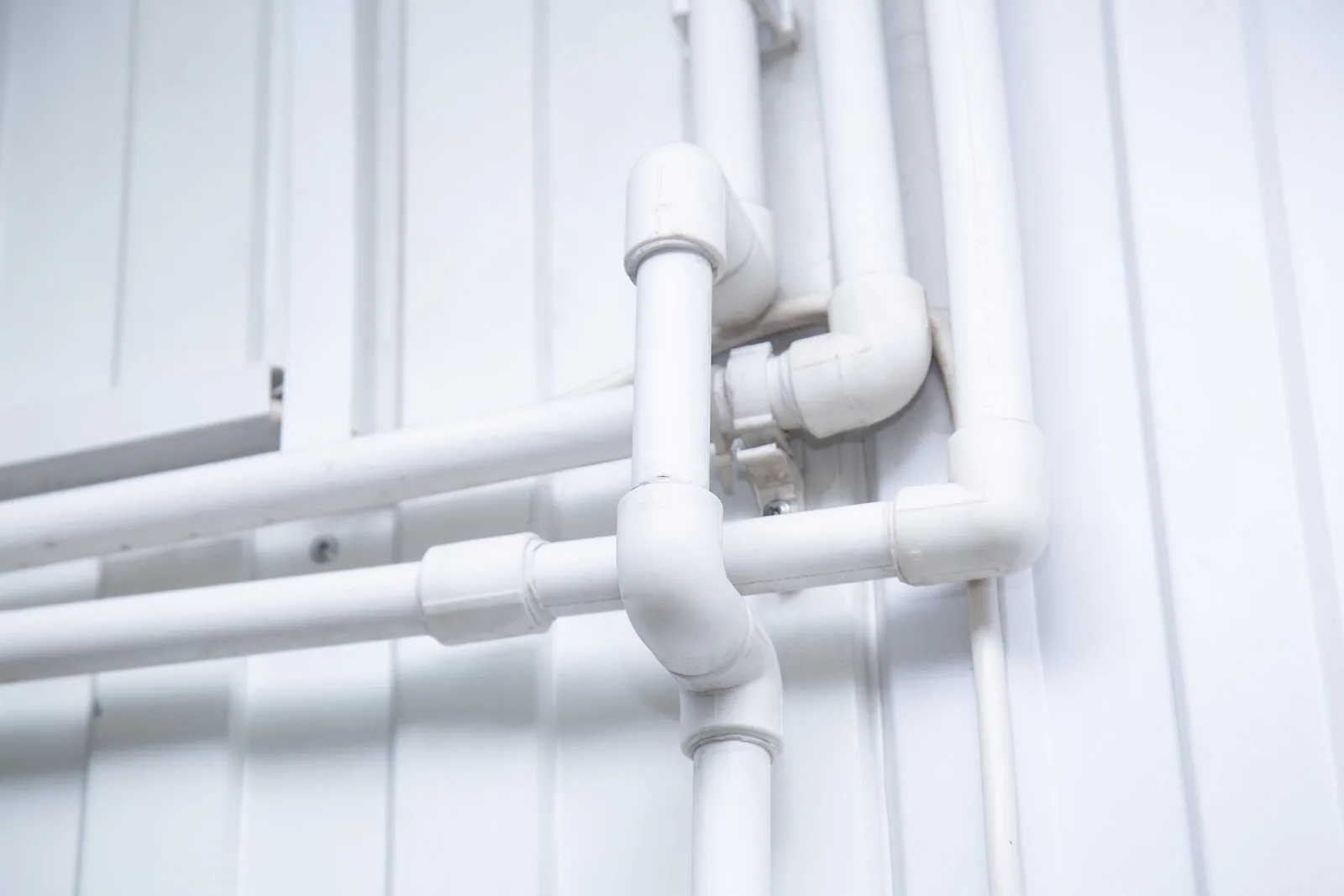
Step 3 — Chase, duct or sleeve: can PPR go straight into cement?
Here two credible authorities disagree, and pretending otherwise would be dishonest.
The material says yes. Aquatherm’s 2024 installer manual, covering PP-R and PP-RCT, states that where pipe needs to be buried in soil, sand or concrete, the material is “safe, non-leaching, and resistant to crushing or damage.” On movement it goes further: buried installations “generally do not require additional consideration for the expansion,” because resistance from the concrete or backfill restricts natural expansion, and PP-R’s expansive force is much lower than that of metal pipes. Thrust blocking is not required in buried applications either, because a fused joint carries its own integrity.
The regulator says no. UK guidance on concealed pipework, citing Schedule 2 paragraphs 7, 8 and 9 of the Water Fittings Regulations, states that concealed domestic hot and cold pipework should not be embedded or come into contact with other materials such as plaster or cement, and should be accessible to enable inspection and replacement. It also rules out a common shortcut: pipework must sit in a chase, duct or void, and wrapping it in insulation is not an acceptable substitute.
Both are true, and they are not arguing about the same thing. One describes what the polymer tolerates; the other, what a national regulator will accept. EN 806-4 clause 3.2.5 anticipates the split with its carve-out — “unless national regulations require accessibility of certain joints” — and EN 806-4’s own installation rules land on the conservative side: except where a pipe is installed in a sleeve, duct or chase, no pipework shall be embedded in any wall or solid floor unless it can be readily removed and replaced.
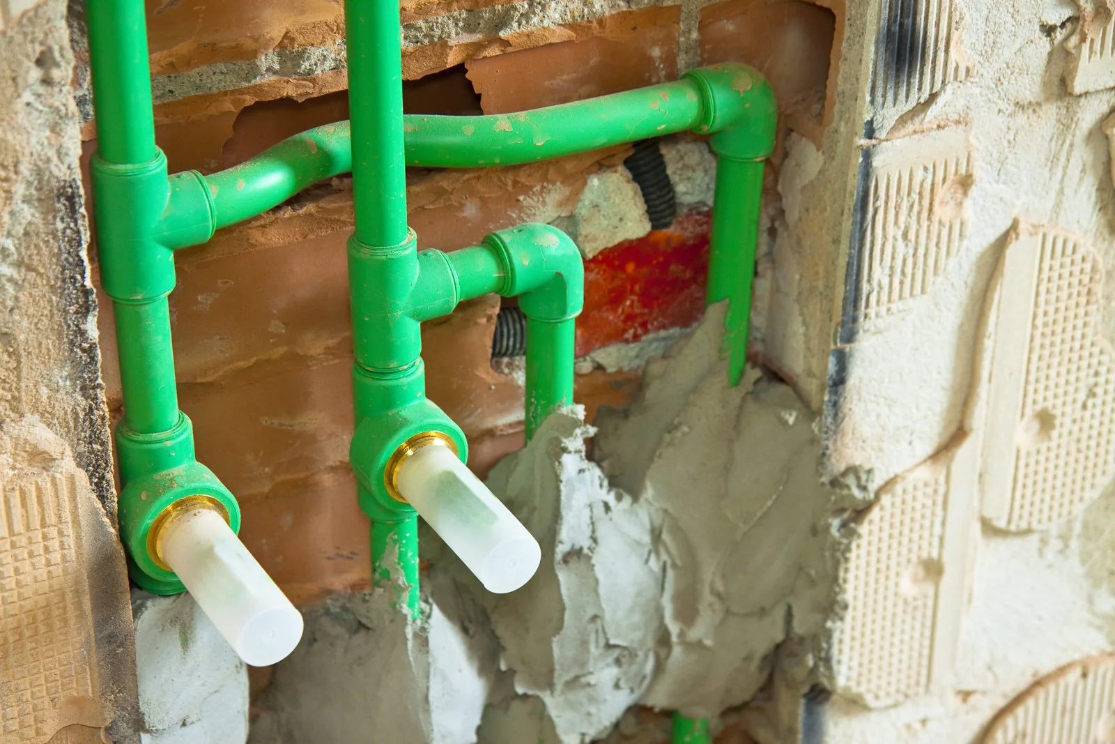
The resolution is not a compromise, it is a method. Install in a chase, duct or sleeve and you are compliant in both regimes at once. It costs almost nothing at first fix, and it is the difference between a wall that can be opened and one that has to be demolished. It also does not change what pipe you buy — pressure class and system standards are chosen on operating temperature and duty, which our PPR pipe range sets out by size and PN rating.
There is an engineering reason too, separate from access. EN 806-4 requires that piping laid through notches, holes, cut-outs or chases shall not be subjected to external forces and shall be free to expand or contract. Pipe troweled into mortar is restrained by definition. In a chase or conduit it can move.
Two details finish the job. Piping passing through walls and floors shall be sleeved — a requirement, not a nicety, and the detail most often skipped where a riser leaves a floor. And where pipes in protective conduit are embedded in the building fabric, EN 806-4 warns that deformation or displacement must not occur and that no liquid concrete may enter the annular gap; protective pipes in floors shall be cut off at least 30 mm above finished floor level. A conduit that fills with grout during the pour has become solid embedment, and you will not know until you try to withdraw the pipe.
Specifying pipe for a concealed run and not sure which grade goes in?
For contractors and specifiers choosing between plain and composite PPR before first fix: the pipe range page lists the pressure classes, dimensions and applicable standards for each system. Useful if you are still deciding what to buy, not yet pricing a container.
See the PPR pipe range Ask a technical questionStep 4 — Clipping, anchoring and the movement you must allow
Supplier blogs like to quote a single clip spacing — 60 to 80 cm is the usual one — with no diameter and no distinction between hot and cold. Treat that number as worthless. Spacing depends on both, and the difference is not small.
Below is Niron’s support distance table from its European technical guide, aligned to UNI EN 806-4. One named manufacturer’s published data rather than a universal law — but diameter-banded and split by service, which makes it the right shape for a decision.
| Pipe OD | Cold water spacing | Hot water spacing |
|---|---|---|
| ≤ 16 mm | 750 mm | 400 mm |
| >16–20 mm | 800 mm | 500 mm |
| >20–25 mm | 850 mm | 600 mm |
| >25–32 mm | 1000 mm | 650 mm |
| >32–40 mm | 1100 mm | 800 mm |
| >40–50 mm | 1250 mm | 1000 mm |
| >50–63 mm | 1400 mm | 1200 mm |
| >63–75 mm | 1500 mm | 1300 mm |
| >75–90 mm | 1650 mm | 1450 mm |
| >90–110 mm | 1900 mm | 1600 mm |
At 25 mm OD the hot figure is 600 mm against 850 mm cold — roughly a third tighter, and at 16 mm closer to half. Warm PPR loses stiffness and sags between supports, so the same pipe carrying 60°C water needs more of them. Clip a hot run at cold-run spacing and you get visible droop and a slow ripple of movement every time the system cycles. For vertical pipes, multiply spacing by 1.3.
Anchoring is the other half. Where the design deliberately prevents thermal movement, Niron’s guide sets the maximum distance between anchor points at 6 m or less — spaced to that limit, not placed by eye. Where an embedded pipe penetrates concrete and may be subject to movement or lateral force, Aquatherm’s manual calls for a shield or protective layer and recommends anchoring at that point.
One caution on expansion arithmetic: coefficients quoted for plain PPR do not apply to fibreglass-composite pipe, which exists specifically to reduce movement on long runs. Running long hot legs and thinking about loops? Changing the pipe usually beats adding geometry. Our fibreglass composite PPR page covers where the composite layer earns its cost.
Fixings decide whether the building becomes an amplifier. Pipe clipped rigidly to structure transmits vibration straight into it, so a resilient layer belongs between pipe and fixing at every support point, with the fixing never touching the pipe directly. Walraven, a fixings manufacturer, attributes a maximum permissible transmitted noise level from pipework to DIN 4109 with a residual value of 35 dB(A). Treat that as the fixing industry’s reading of the standard rather than something read from DIN 4109 itself — the principle stands regardless of the number.
How wide and deep does the chase need to be once the pipe is insulated?
Wider and deeper than the pipe alone suggests: a 20 mm hot PPR pipe with the insulation German energy law requires needs a chase about 50 mm wide and 40 mm deep, which already exceeds the 30 mm post-cut depth Eurocode 6 allows without calculation. Insulation, not pipe diameter, is what pushes a concealed hot run out of the no-calculation zone.
The depth tables earlier on this page were written for the bare pipe. On a hot-water run the pipe does not go in bare. Germany’s Gebäudeenergiegesetz, Anlage 8, sets the minimum insulation on hot-water and heating pipes by internal diameter: 20 mm for an inner bore up to 22 mm, 30 mm from 22 to 35 mm, equal to the bore from 35 to 100 mm, all at a thermal conductivity of 0.035 W/(m·K); where the pipe runs in a wall or ceiling between heated rooms, half of those values apply, and in a floor build-up 6 mm is enough. Other countries set different thicknesses, but every hot-water regime adds something around the pipe, and the chase has to be cut for pipe plus insulation plus a clip.
| Pipe OD (mm) | Insulation, in wall between heated rooms / full (mm) | Chase width needed (mm) | Chase depth needed vs 30 mm post-cut limit (mm) | Expansion on a 3 m leg at ΔT 40 K, PP-R / fibre-composite (mm) |
|---|---|---|---|---|
| 20 | 10 / 20 | 50 / 70 | 40 / 60 — over the limit either way | 18 / 4.2 |
| 25 | 10 / 20 | 55 / 75 | 45 / 65 — over the limit | 18 / 4.2 |
| 32 | 10 / 20 | 62 / 82 | 52 / 72 — over the limit | 18 / 4.2 |
| 40 | 15 / 30 | 80 / 110 | 70 / 100 — formed chase or duct only | 18 / 4.2 |
| Bare cold pipe, 20–25, for comparison | 0 (condensation wrap where required) | 30–35 | 20–25 — inside the limit | Negligible at cold-water ΔT |
| Sources: GEG Anlage 8 (zu §§ 69 und 70), gesetze-im-internet.de, insulation by inner diameter at λ = 0.035 W/(m·K), halved in components between heated rooms; EN 1996-1-1:2005+A1:2012 § 8.6.2, 30 mm maximum depth for chases cut after construction; PPR bores from the SDR 6 wall thickness in DIN 8077:2008-09; α = 0.15 mm/(m·K) for PP-R and 0.035 mm/(m·K) for glass-fibre composite per manufacturer data (SPK Pipe & Fittings, spk.com.tr/en/Article/38676); ΔL = α × L × ΔT. Width = OD + 2 × insulation + 10 mm clip play; depth = OD + 2 × insulation. Our arithmetic, rounded. | ||||
Two things follow. First, an insulated hot drop cannot legally go into a chase cut after construction in a 100 mm leaf without a structural calculation — the pipe fits, the insulated pipe does not. Either form the chase during construction, where an 85–115 mm wall keeps a 70 mm minimum remaining thickness and the recess can be far deeper, or run the hot leg in a duct, a stud partition or the floor build-up. Second, the width column explains why insulated runs get squeezed: the installer cuts for the pipe, the insulation gets compressed or stripped at the clip, and the wall ends up warm in a line. Compressed insulation is not insulation.
The expansion gap: what the last column is for
A 3 m hot leg of plain PP-R grows about 18 mm between a cold fill and 60 °C service. Inside a chase that movement has nowhere to go except into the elbow at each end, so a concealed run needs one of three things: a fixed point at the tee with the free arm long enough to flex, a compressible wrap around the pipe so the chase filling does not lock it, or fibre-composite pipe, which cuts the figure to about 4 mm and usually removes the problem. The spacing rules and loop geometry for the exposed case are worked through in our thermal expansion and support spacing guide; for the concealed case the answer is almost always the third option. Whatever is chosen, the sleeve where the pipe leaves the wall must have a real annular gap — EN 806-4:2010 requires the pipe to be free to expand and contract in the sleeve, and a sleeve packed with mortar is a fixed point nobody designed.
One edition note for specifiers citing the Eurocode clauses on this page. The chase limits quoted here are from EN 1996-1-1:2005+A1:2012, which remains the operative edition in most national annexes; the second-generation EN 1996-1-1:2022 has been published (BSI, August 2023) and will take over as national annexes are issued, so a specification should name the edition it relies on. The pressure test that closes the wall, and the record that goes with it, are set out step by step in our EN 806-4 pressure test guide; the wall thicknesses that the bore figures above rest on are the DIN 8077 tables published by DIN.
Step 5 — The pressure test that closes the wall
This is the step clause 3.2.5 was written for. The test happens after installation is complete but while the pipework is still exposed — not after the plasterer has been, and not “when there’s a gap in the programme.” DIN EN 806-4 Section 6 requires pressure testing of drinking water pipes with filtered water once installation is finished and while the pipe is still visible, with the gauge connected at the lowest point in the system.
It is two tests, not one. First the installation is checked for leak-tightness, then for strength. Testing can use water or compressed air. Running them as a single event is the most common way an installer convinces himself he has tested when he has done half the job.
Now the number, and the honest answer is that there is no global one — test pressure depends on the regime you work under. Under BS EN 806 it is 1.1 × MDP, where MDP is 1.5 × the maximum operating pressure. UK water regulators publish the comparison directly: for a system at 5 bar operating pressure, the Regulations and Byelaws approach gives 1.5 × 5 = 7.5 bar, while BS EN 806 gives 1.1 × 8.25 bar. Because the EN figure is higher, an installation designed to satisfy the BS EN 806 pressure test recommendations complies with the Water Fittings Regulations by default. Anyone quoting one universal “test at 1.5× or 2×, minimum X MPa” rule is describing a single jurisdiction and calling it the world.
Two procedural details decide whether the result means anything. Temperature equalisation is required where the difference exceeds 10 K, so system temperature should match the test medium — fill a cold system with warm water and the pressure drifts as it equalises, and you chase a leak that does not exist. And only gauges indicating a pressure difference of 0.1 bar may be used. A coarser gauge cannot demonstrate tightness however long you watch it.
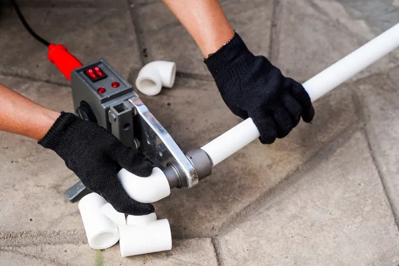
What the test does not prove: that the joint was correctly fused. A cold or under-heated socket fusion joint can pass a pressure test and fail two years later, which is why heating time, insertion depth and unstressed cooling matter as much as the test that follows. We cover the fusion parameters in the socket fusion welding guide.
Step 6 — Signing off a joint nobody will ever see again
The regulator’s view of concealed joints is blunt: joints on concealed pipework are likely to lose their integrity over time and should only be considered where unavoidable. Read that as a design instruction, not a warning — the first question at first fix is not how to make the buried joint well, it is how to have fewer of them. There is also no verified maximum concealed run length for PPR and no mandated access-hatch interval, so anyone quoting you one has invented it.
Before the plasterer arrives, a record has to exist. What a QS can actually sign against:
- Photographs of every joint in the chase, with a tape in frame showing position from a permanent datum such as a door reveal — so the joint can be found again without opening the whole wall.
- The pressure test record: medium, test pressure and the operating pressure it derives from, start and end readings, duration, gauge resolution, and temperature of system and medium.
- Confirmation that both stages ran — leak-tightness and strength — not one combined figure.
- Chase depths and wall thicknesses where they approach the Eurocode 6 limits, plus any location where a structural calculation was obtained.
- Pipe and fitting batch identification, so a future claim traces to a production run rather than a guess.
That last point is where the product starts to matter. Bekaatherm carries a 50-year warranty against material and manufacturing defects, matched to the 50-year design life at rated pressure and 20°C under ISO 15874. A warranty of that length only means anything if the batch inside the wall can still be identified in year twelve — which is an argument for recording marking data at first fix, not a marketing point.
How we check a system before it ships
The documentation you rely on at sign-off starts upstream. What we hold for the pipe going into your wall:
- Product standards named explicitly — ISO 15874-1 (general), -2 (pipes), -3 (fittings) and -5 (fitness for purpose of the assembled system), with dimensions and wall thickness to DIN 8077 and general quality requirements to DIN 8078.
- Third-party certification against SKZ (Germany), ISO 15874, CE and WRAS — listed on our certifications page so a specifier can check scope rather than take a logo on trust.
- Pipe and fitting supplied as one system, because ISO 15874-5 assesses the whole assembly, not a pipe on its own. Mixing brands at the joint moves that assessment outside anything either supplier tested.
One currency note for specifiers. ISO 15874-5:2013 is the second edition, published February 2013 with a corrected version in January 2015, and it is under revision, but as of September 2026 the revision is still a committee draft (ISO/CD 15874-5), so ISO 15874-5:2013 with Amendment 1:2018 remains the edition to cite. ISO 15874-2:2013 remains the base pipe standard, amended by Amendment 1:2018 and Amendment 2:2022 covering impact testing. Citing edition numbers in a specification? Check current status at iso.org before issuing rather than copying from a datasheet.
One bathroom, start to finish
A second-floor bathroom. Internal partitions are 100 mm blockwork; the corridor wall is 225 mm. Hot and cold feeds arrive at the corridor wall, and the partition needs outlets for a basin, a WC and a shower.
Horizontal distribution never enters the partition, because permitted depth there is zero — the cross-room run goes in the floor build-up, decided at planning rather than when someone is standing at the wall with a chaser. Vertical drops feed each outlet from the floor at 30 mm deep and 100 mm wide; at 20 mm OD the pipe plus clip fits, and the check is that nothing protrudes past the wall face. Basin and WC drops keep 225 mm from each other and from the door opening, and the shower drop moves 200 mm off the corner to clear the electrician’s cable zone.
Each drop runs from the floor manifold connection to the outlet elbow in one length: three drops, three concealed joints at the outlets, zero mid-run joints in the wall. Where pipe crosses from screed into the partition it passes through a sleeve. Clips go in at 500 mm on the 20 mm hot leg against 800 mm cold, times 1.3 for vertical, with a resilient layer at every fixing.
Then the test, and only then the plasterer. System and test water within 10 K, gauge reading to 0.1 bar, connected at the lowest point, both stages recorded, photographs with a tape against the door reveal. The chase is filled and reinforced over the pipe so nothing sits proud. Plaster cracks in a line along a buried hot pipe because a warm pipe moves and a thin skim over a hard pipe back telegraphs that movement to the surface. Cut deep enough that the pipe sits below the wall face and the crack has nothing to follow.
Best for / not for: when to conceal at all
Concealment is a choice, and it is not always the right one.
Concealed chasing works best on vertical drops in walls of 175 mm or more, where the chase depth allowance is comfortable; on runs that can be made joint-free from manifold to outlet; on cold-water feeds, where movement is smallest and clip spacing most forgiving; and on new-build work where the chase can be formed during construction rather than cut afterwards, which multiplies the permitted depth several times over.
Concealment is the wrong answer for horizontal runs in any leaf of 115 mm or less, where the permitted depth is zero; for any run needing mid-length joints; in reinforced masonry or through lintels, where Eurocode 6 rules it out; on short piers between openings, where the 225 mm and 500 mm spacing rules leave nowhere legal to cut; and in jurisdictions requiring joint accessibility, unless a duct or hatch is designed in from the start.
Where concealment fails those tests, the honest options are a service duct, a boxed run, a stud partition, or routing through the floor. All look like more work at first fix. All cost less than opening a plastered wall later. Requirements vary by country and building type, so confirm the applicable national rules with your building control body or water undertaker before finalising a concealment strategy — the standards quoted here are European and UK, and adoption differs by market.
Pricing pipe for a project with concealed runs?
For contractors and buyers working to a bill of quantities: send the sizes, pressure class and quantities and our technical team will confirm what fits the concealed sections and what the applicable standards require. Best used once you have a drawing, not at concept stage.
Send your pipe schedule Browse fittings rangeFrequently asked questions
How deep can I cut a chase in a wall for a PPR pipe?
For a chase cut after construction, EN 1996-1-1 §8.6.2 allows a vertical chase up to 30 mm deep in every wall thickness band from 85 mm upwards, without structural calculation. Only the permitted width increases with wall thickness, from 100 mm to 200 mm. UK Approved Document A 2C30 expresses it as 1/3 of the leaf thickness for vertical chases.
Can I cut a horizontal chase in a 100 mm block wall?
Not without a structural calculation. EN 1996-1-1 §8.6.3 gives a permitted horizontal chase depth of zero for walls of 85–115 mm, at any chase length. Horizontal chasing only becomes permissible without calculation at 176 mm wall thickness and above, and even then at 10 mm for unlimited length.
Can PPR pipe be embedded directly in plaster or cement?
The material tolerates it, but the regulations may not allow it. EN 806-4 requires pipework to sit in a sleeve, duct or chase unless it can be readily removed and replaced. UK guidance on concealed pipework goes further and states that pipework should not be embedded or come into contact with plaster or cement, and should remain accessible for inspection and replacement. Installing in a chase or duct satisfies both positions.
Do I need expansion loops on PPR embedded in a wall or screed?
Generally not in the buried section itself. Aquatherm’s installer manual states that buried installations generally do not require additional consideration for expansion, because resistance from the concrete or backfill restricts natural movement, and PP-R’s expansive force is much lower than that of metal pipes. Where movement is prevented by design, the maximum distance between anchor points should be 6 m or less.
At what pressure should I test PPR before plastering?
It depends on the regime that applies. Under BS EN 806 the test pressure is 1.1 × MDP, where MDP is 1.5 × the maximum operating pressure — for a 5 bar system that gives 1.1 × 8.25 bar, against 7.5 bar under the UK Water Fittings Regulations approach. Because the EN figure is higher, satisfying BS EN 806 complies with the Regulations by default. Confirm which regime governs your site before fixing a figure.
How far apart should PPR pipe clips be?
It varies by diameter and by whether the line is hot or cold. Niron’s table aligned to UNI EN 806-4 gives 850 mm cold and 600 mm hot at 20–25 mm OD, and 1000 mm cold against 650 mm hot at 25–32 mm. Hot spacing is tighter because warm pipe sags more between supports. For vertical pipes, multiply the figure by 1.3.
Why does plaster crack in a line above a buried hot water pipe?
A hot pipe moves as the system cycles, and a thin layer of plaster over a hard pipe back transmits that movement to the surface. No standard consulted here fixes a minimum cover thickness over a water pipe, so treat any millimetre figure you see quoted with caution. The executable rule is to cut the chase deep enough that pipe, clip and sleeve all sit below the wall face, then fill and reinforce over it rather than skimming over a proud pipe.
Does PPR need to be sleeved where it passes through a wall or floor?
Yes. EN 806-4 states that piping passing through walls and floors shall be sleeved. Where pipes in protective conduit are embedded in the building fabric, the standard also requires that no liquid concrete enters the annular gap, and that protective pipes in floors be cut off at least 30 mm above finished floor level to prevent liquid ingress.