Almost every pipe sizing guide in English sizes in copper. That leaves a specifier working in PP-R with a bad choice: size the copper, then pick the PPR pipe with the same outside diameter. The standard’s own tables show why that fails. Copper 28 x 1,5 has an internal diameter of 25 mm; PP-R 50 x 8,4 has 33,2 mm. The plastic pipe carries its wall on the inside, so matching the OD hands you a bore two sizes short.
EN 806-3:2006 does publish a PP column, in Table 3.6, and it takes you from a loading-unit total straight to a PP-R diameter with no copper detour. This page reproduces that column, then works a six-dwelling riser through it section by section, so a reviewer can check every step against the clause it came from.
Key Takeaways
- EN 806-3:2006 is the simplified sizing method for drinking water inside buildings, prepared by CEN/TC 164 and approved by CEN on 3 February 2006. Clause 1 states it applies in conjunction with EN 806-1 and EN 806-2 — Part 3 alone is an incomplete basis.
- One loading unit (LU) equals a draw-off flow rate of 0,1 l/s. A washbasin or WC cistern is 1 LU, a shower head or kitchen sink 2 LU, a domestic bath 4 LU (EN 806-3 Table 2).
- Do not apply a diversity factor on top of the LU total. Clause 5.5: “the probability of simultaneous demand has been taken into consideration in Tables 3.1 to 3.8.” Discounting twice undersizes the riser.
- The sizing tables are built on maximum velocities of 2,0 m/s in header, rising and floor service pipes, and 4,0 m/s in a connection pipe to a single fitting.
- In Germany, DIN 1988-300 limits the simplified route to residential buildings of up to six dwellings. Above that, the differentiated method is required — the most common scope error in this topic.
- EN 806-3 Clause 5.3 excludes hot water return pipes: “they cannot be sized with this method.” Clause 1 also excludes firefighting systems.
- PN 20 is a 20 °C rating. Under ISO 15874 application classes, the allowable operating pressure of a PP-R SDR 6 wall drops to 8 bar at Class 2 (70 °C hot water) and 6 bar at Class 5 (80 °C heating).
- Loading units and US water supply fixture units are parallel, non-interchangeable systems. No published conversion factor exists between them.
Which method are you allowed to use?
Before any arithmetic, one gate question: is this a standard-installation? EN 806-3 defines the term in three conditions, and failing any one puts the job outside the simplified method entirely.
An installation qualifies when the draw-off flow rates do not exceed those in Table 2, the demand does not exceed the design flow rate in Figure B.1, and it is not designed for continuous use of water — which the standard fixes at use lasting more than 15 minutes. Anything else is a special-installation, and Clause 5.2 sends you elsewhere: “the designer is free to use a nationally approved detailed calculation method for pipe sizing,” with Annex C listing national methods informatively.
The 15-minute rule catches more buildings than people expect. A gym shower block, a laundry, an irrigation header — each runs past fifteen minutes routinely. Anything with a plausible continuous duty belongs in the detailed method.
The six-dwelling ceiling
The limit that catches specifiers lives in the national layer, not in EN 806-3 itself. DIN 1988-300 permits the simplified route only “for residential buildings with up to six dwellings,” and only where the mains pressure is adequate and acceptable water hygiene is ensured. Every other drinking water installation is sized by the differentiated method.
That ceiling is not arbitrary. The German commentary notes that with six dwellings a maximum total flow of about 60 LU is reached depending on sanitary fit-out, so the curve could reasonably be cut there — Figure B.1 runs out to 300 LU only to show the trend. Outside Germany, treat this as the shape of the risk rather than a rule that binds you. Check what your own authority having jurisdiction says before relying on the simplified route for an eight-storey block. A calculation an inspector rejects on scope grounds is a calculation you did twice.
Best for / not for
Best for: single dwellings, small apartment blocks within the national dwelling ceiling, straightforward branch and riser layouts with tabulated fixtures, and any job where you need a defensible size fast and the mains pressure is comfortable.
Not for: hot water circulation loops, firefighting mains, anything with a continuous draw over 15 minutes, buildings above the national dwelling limit, marginal supply pressure, or fixtures whose flow rates exceed Table 2. All of those belong to a detailed method such as DIN 1988-300.
The pressure pre-check that decides it
Most English-language sizing pages skip this step, which is why so many simplified calculations are technically inadmissible. The tables assume pressure to spare. If the incoming main is weak, the simplified route is not conservative — it is invalid, and you find out at commissioning.
Start from the two pressure conditions the standard sets at the draw-off point. Static pressure must not exceed 500 kPa, with garden and garage taps allowed up to 1 000 kPa. Flow pressure must be at least 100 kPa. The standard adds a warning worth reading twice: “several draw off points, e.g. thermostatic mixing valves, need a higher flow pressure. Calculations have to consider this matter.” A shower with a thermostatic cartridge is not a 100 kPa fixture.
The German commentary works the check as a subtraction. Take the minimum supply pressure, then strip out everything that eats it before the tap.
| Line item | Value (hPa) |
|---|---|
| Minimum supply pressure pminV | 4 000,0 |
| Less house connection loss | 850,0 |
| Less geodetic head (static lift to the top outlet) | 800,0 |
| Less apartment water meter | 200,0 |
| Less filter | 200,0 |
| Less minimum flow pressure at a washbasin mixer | 500,0 |
| Available for friction and single resistances | 1 450,0 |
| Assumed share for single resistances | 40,0 % |
| Available for pipe friction over 29,0 m | 870,0 |
| Available friction gradient R | 30,0 hPa/m |
The pass criterion is a single line, and it is the one to memorise: the minimum supply pressure is deemed sufficient if R exceeds 10 hPa/m. At lower values the calculation must be done per DIN 1988-300. In the worked figures above, R lands at 30,0 hPa/m — three times the threshold, so the simplified tables are legitimate here.
Two deductions are where sites actually fail. Geodetic head is fixed by the building and nothing you specify changes it. The 40 % allowance for single resistances is an assumption, not a measurement — a branch-heavy layout with a dozen elbows per dwelling burns more. When R lands anywhere near 10 hPa/m, treat that as a prompt to run the detailed method rather than a pass.
R > 10 hPa/m is the gate. Below it, the simplified table is not a conservative shortcut — it is the wrong method, and no amount of oversizing the riser fixes an inadequate main.
Loading units: the input table
A loading unit is a bookkeeping device. EN 806-3 Table 1 defines it as a factor taking into account the flow rate required at an appliance, how long it is in use, and how often. One LU equals a draw-off flow rate QA of 0,1 l/s, and everything else in Table 2 scales from there.
| Fixture | QA (l/s) | Qmin (l/s) | Loading units |
|---|---|---|---|
| Washbasin, handbasin, bidet, WC cistern | 0,1 | 0,1 | 1 |
| Domestic kitchen sink, washing machine, dishwasher, sink, shower head | 0,2 | 0,15 | 2 |
| Urinal flush valve | 0,3 | 0,15 | 3 |
| Bath, domestic | 0,4 | 0,3 | 4 |
| Taps, garden or garage | 0,5 | 0,4 | 5 |
| Non-domestic kitchen sink DN 20, bath non-domestic | 0,8 | 0,8 | 8 |
| Flush valve DN 20 | 1,5 | 1,0 | 15 |
Now the trap, printed as a note beneath that table: “the values in this Table do not correspond with the values in product norms. They are only used for pipe sizing.” A tap whose product standard declares 0,25 l/s is still a 2 LU fixture here. Cross-referencing a manufacturer’s flow figure into the sizing total is a mistake that looks like diligence.
Note also how hard non-domestic fixtures jump. One DN 20 flush valve at 15 LU outweighs an entire small apartment.
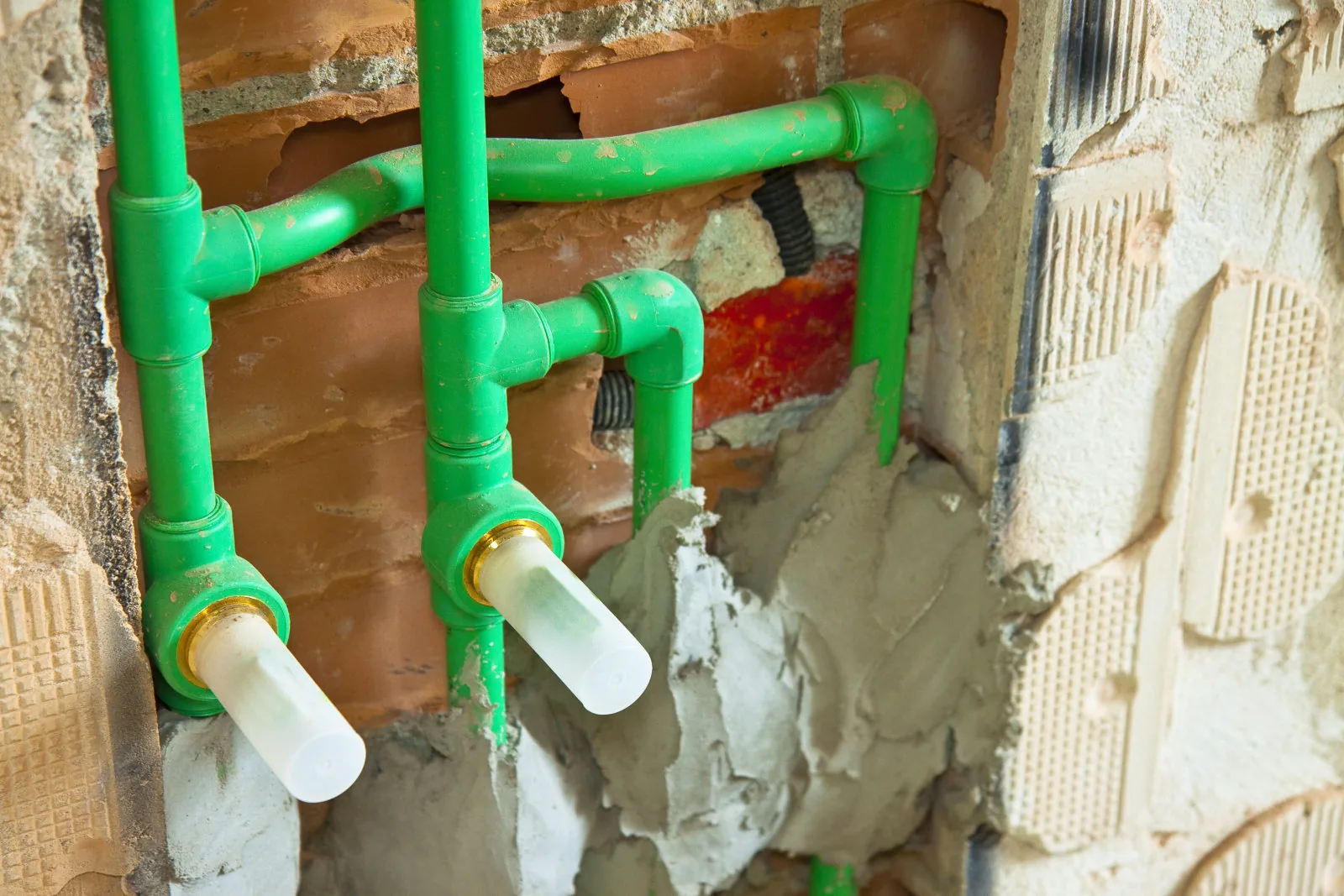
The PP column of EN 806-3 Table 3
EN 806-3 gives Tables 3.1 to 3.8, one per material. Table 3.6 is polypropylene — the one you want for PP-R. Below are its dimension pairs and internal diameters as the standard prints them, alongside copper and PE-X for comparison.
| PP da x s (mm) | PP di (mm) | Nearest copper di | Nearest PE-X di |
|---|---|---|---|
| 16 x 2,7 | 10,6 | 10,0 (12 x 1,0) | 11,6 (16 x 2,2) |
| 20 x 3,4 | 13,2 | 13,0 (15 x 1,0) | 14,4 (20 x 2,8) |
| 25 x 4,2 | 16,6 | 16,0 (18 x 1,0) | 18,0 (25 x 3,5) |
| 32 x 5,4 | 21,2 | 20,0 (22 x 1,0) | 23,2 (32 x 4,4) |
| 40 x 6,7 | 26,6 | 25,0 (28 x 1,5) | 29,0 (40 x 5,5) |
| 50 x 8,4 | 33,2 | 32,0 (35 x 1,5) | 36,2 (50 x 6,9) |
| 63 x 10,5 | 42,0 | 39,0 (42 x 1,5) | 45,6 (63 x 8,6) |
| 75 x 12,5 | 50,0 | 50,0 (54 x 2,0) | — |
Read the first and third columns together and the OD-substitution error becomes obvious. Copper 28 x 1,5 gives 25 mm of bore; the PP-R pipe that matches it hydraulically is 40 x 6,7, not 28-anything. Write “PPR equivalent” against a copper schedule without going through internal diameter and you ship a riser roughly two nominal sizes light.
Table 3.6 carries two more rows that matter. The first is maximum load in loading units per column, which is how you enter the table. The second is a maximum length of pipe, and for PP the tabulated limits across the smaller columns run 20, 12, 8, 15, 9 and 7 metres. Exceed the tabulated length in a section and the simplified table stops covering it. The standard prints these without rationale, so take them as a boundary, not something to interpolate.
The highest-single-value rule
Table 3 does not only ask for the sum. It also carries a “highest single value LU” row, which caps the largest individual fixture a given column may serve. For PP that row shows values including 2 at the 3 LU column, then 4, 5 and 8 further along.
A single large fixture can force a size increase even when the total is small. That is the mechanism behind a point UK guidance raises but rarely demonstrates: four baths at 4 LU each totalling 16 LU does not size the same as eight showers at 2 LU each also totalling 16 LU. BS 8558:2015 is described as simpler precisely because it does not factor in the largest fixture loading unit, and generally yields higher flow rates as a result.
Check both rows on every section. Sum, then largest fixture, then take whichever column satisfies both.
Worked example: a six-dwelling riser in PP-R
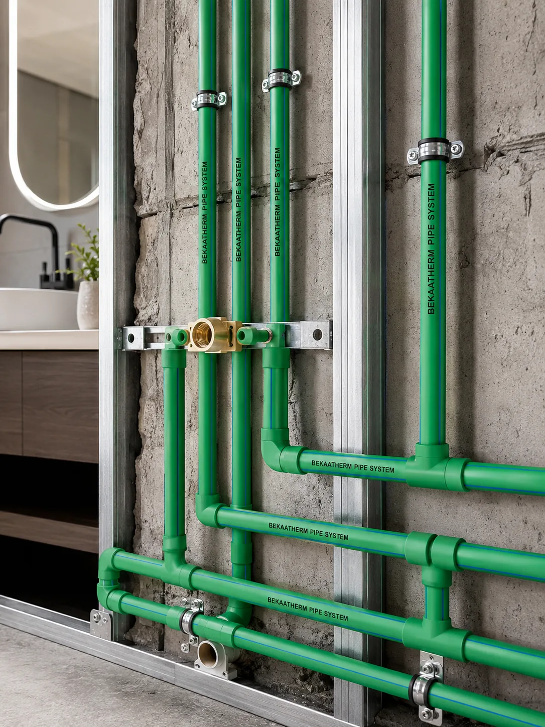
Take the building the German commentary uses, and size it in PP-R rather than copper. Six identical dwellings on one cold water riser, each with a kitchen sink at 2 LU, a bath at 4 LU, a washbasin at 1 LU and a WC cistern at 1 LU — 8 LU per dwelling.
The procedure comes straight from Clause 5.5. Begin at the last draw-off point, determine the loading units for each section, add them, then read the size from the table for your material. The clause is explicit that you do not adjust further: “the probability of simultaneous demand has been taken into consideration in Tables 3.1 to 3.8.” A diversity factor on top of the total is double-discounting, and it undersizes the riser.
| Section | Cumulative LU | Largest single fixture | PP-R size read from Table 3.6 |
|---|---|---|---|
| Connection to kitchen sink | 2 | 2 LU | 20 x 3,4 (di 13,2) |
| Branch serving sink + bath | 6 | 4 LU (bath) | 20 x 3,4 (di 13,2) — 6 LU column; its single-fixture cap admits the 4 LU bath |
| Dwelling supply, one flat | 8 | 4 LU (bath) | 25 x 4,2 (di 16,6) — 13 LU column, single-fixture cap 8 LU |
| Riser above flat 5 (2 flats) | 16 | 4 LU | 32 x 5,4 (di 21,2) — 30 LU column |
| Riser above flat 3 (4 flats) | 32 | 4 LU | 40 x 6,7 (di 26,6) — 30 LU exceeded, next column is 70 LU |
| Riser base, all 6 flats | 48 | 4 LU | 40 x 6,7 (di 26,6) — still inside the 70 LU column |
These sizes are a reading of the reproduced table by the Clause 5.5 procedure, not values the standard prints as answers. The commentary’s own example is published in copper; the PP-R results above are what Table 3.6 gives for the same fixture schedule. Check them against your own copy before they go on a drawing.
Two steps are worth pausing on. At 48 LU the riser base still sits inside the 70 LU column, so the whole riser from the third-floor take-off down runs in 40 x 6,7; the 30 LU column, 32 x 5,4, covers only the top two flats. You do not interpolate between columns, you step up at the boundary, and Table 3.6 places its boundaries at 13, 30, 70 and 200 LU for the 25, 32, 40 and 50 mm sizes respectively, with 16 x 2,7 and 20 x 3,4 spanning the short connection-pipe columns. The 6 LU branch is where the highest-single-value rule has to be shown: the sum lands in the 6 LU column at 20 x 3,4, and that column’s cap admits the 4 LU bath. Write the cap check on the sheet. An inspector who sees only the sum cannot tell whether you did it. and 70 LU columns, so it takes the 70 LU column at 50 x 8,4 — you do not interpolate, you step up. And the 6 LU branch is where the highest-single-value rule bites: the sum points at 25 x 4,2, but the 4 LU bath has to be permitted by that column’s cap, and on some readings of the row it is not. Show that check on the sheet. An inspector who sees only the sum cannot tell whether you did it.
What we check before a size goes on a submittal
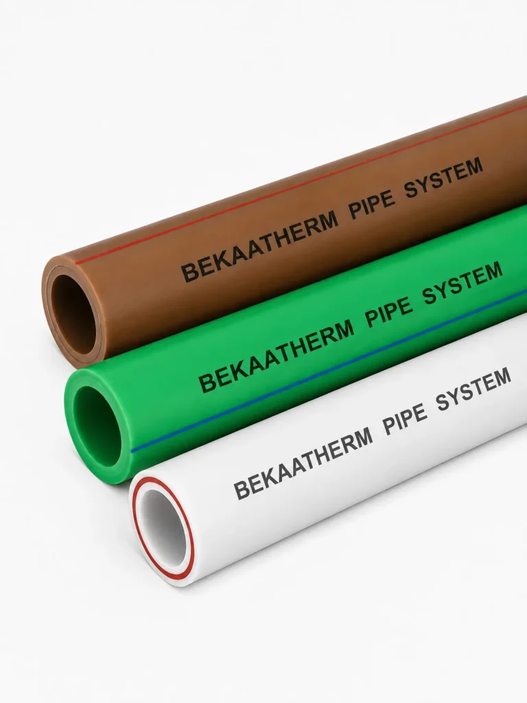
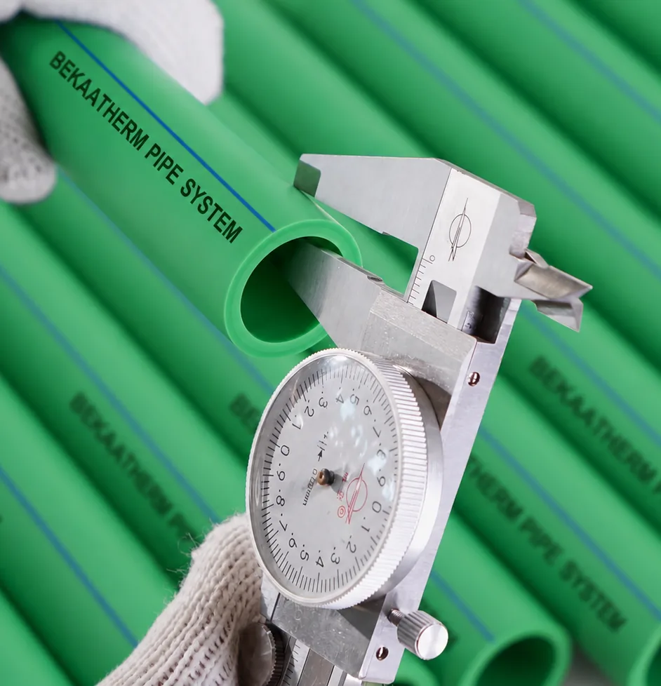
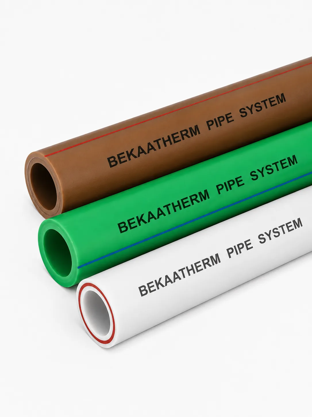
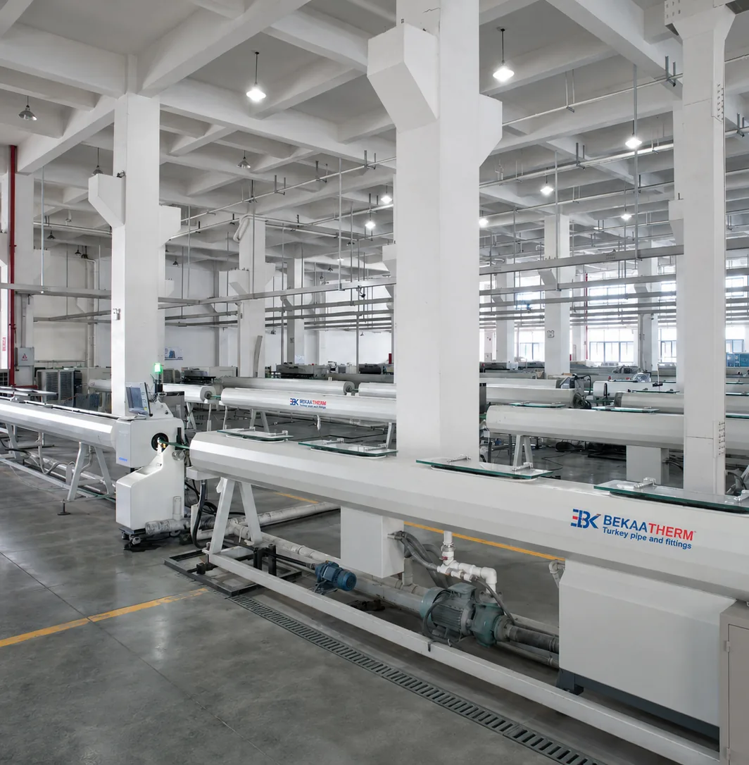
Sizing produces a diameter and a wall thickness. Whether the delivered pipe matches those two numbers is a separate question, and it is the one that fails on site. Bekaatherm builds PPR pipe dimensionally to DIN 8077 with general quality requirements to DIN 8078, and to ISO 15874-1, -2, -3 and -5 across the system, under SKZ, ISO 15874, CE and WRAS certification. Wall thickness is measured with a caliper on the line rather than assumed from the extruder setting, because di is what the sizing table specified — a wall running 0,5 mm heavy on a 25 mm pipe takes a millimetre out of the bore.
Three things belong in a submittal alongside the calculation: the dimension standard the pipe is made to, the certification scheme with its scope, and the application class the wall is rated for. A specifier with all three can defend the size. One with a PN number and a colour cannot. Before a diameter goes on a drawing, check it against the outside diameters and wall thicknesses in the PPR pipe range — a column you read off Table 3.6 is only useful if the size is actually produced in the pressure series you need.
What changes when the block has twelve dwellings?
Two things: the riser base crosses a column boundary in Table 3.6, and in Germany the simplified method is no longer permitted at all, because DIN 1988-300 caps it at six dwellings. Outside Germany EN 806-3:2006 still applies, but the simultaneity it hides is worth checking by hand.
Take a four-storey block with three dwellings per floor on one cold riser. This time the bathrooms have showers instead of baths: kitchen sink 2 LU, shower 2 LU, washbasin 1 LU, WC cistern 1 LU, so 6 LU per dwelling and a largest single fixture of 2 LU. The floor branch serves three dwellings; the riser picks up one floor at a time on the way down.
| Section | Dwellings served | Cumulative LU | Table 3.6 column (max LU) | PP-R size da × s (di, mm) |
|---|---|---|---|---|
| Dwelling supply | 1 | 6 | 6 | 20 × 3,4 (13,2) |
| Floor branch | 3 | 18 | 30 | 32 × 5,4 (21,2) |
| Riser below floor 4 | 3 | 18 | 30 | 32 × 5,4 (21,2) |
| Riser below floor 3 | 6 | 36 | 70 | 40 × 6,7 (26,6) |
| Riser below floor 2 | 9 | 54 | 70 | 40 × 6,7 (26,6) |
| Riser base | 12 | 72 | 200 (70 exceeded) | 50 × 8,4 (33,2) |
| Source: EN 806-3:2006 Table 2 (loading units) and Table 3.6 (PP), read by the Clause 5.5 procedure; column boundaries 6 / 13 / 30 / 70 / 200 LU. Largest single fixture 2 LU clears every cap. A reading of the reproduced table, not values the standard prints as answers. | ||||
The base is the instructive row. Seventy-two loading units is two units over the 70 LU column, and the standard does not interpolate, so the riser steps from 40 × 6,7 to 50 × 8,4 for the last storey. Whether that step is real or an artefact of the column edge is exactly the question the differentiated method answers.
Making the simultaneity visible
Clause 5.5 says the probability of simultaneous demand is already inside Tables 3.1 to 3.8, which is why you never apply a diversity factor to the LU sum. DIN 1988-300:2012-05 shows the same effect explicitly. It converts the sum of the design flows ΣV̇R into a peak flow with V̇S = a · (ΣV̇R)b − c, using a = 1,48, b = 0,19 and c = 0,94 for residential buildings, valid from 0,2 to 500 l/s. With the DIN 1988-300 design flows for the same four fixtures (sink 0,07, shower 0,15, washbasin 0,07, WC cistern 0,13 l/s), each dwelling contributes 0,42 l/s.
| Dwellings (LU) | ΣV̇R (l/s) | Peak V̇S (l/s) | Simultaneity V̇S / ΣV̇R | Velocity in the Table 3.6 size (m/s) |
|---|---|---|---|---|
| 3 (18) | 1,26 | 0,61 | 0,48 | 1,72 in 32 × 5,4 |
| 6 (36) | 2,52 | 0,82 | 0,33 | 1,48 in 40 × 6,7 |
| 9 (54) | 3,78 | 0,97 | 0,26 | 1,74 in 40 × 6,7 |
| 12 (72) | 5,04 | 1,07 | 0,21 | 1,24 in 50 × 8,4 (1,93 if left at 40 × 6,7) |
| Source: DIN 1988-300:2012-05 peak-flow equation and residential coefficients (a 1,48; b 0,19; c 0,94) and its design flows per draw-off point; velocities calculated from the EN 806-3 internal diameters. Velocity check only; the DIN method then runs the pressure-loss calculation, which is what usually decides. | ||||
Simultaneity falls from about one fixture in two running with three dwellings to one in five with twelve; that curve is what Figure B.1 of EN 806-3 draws and what Table 3.6 has already digested. The last row shows why the table steps up: left in 40 × 6,7 the base runs at 1,93 m/s, inside the 2,0 m/s basis but with no margin. The step to 50 × 8,4 buys 1,24 m/s and a quieter shaft at the cost of about 0,3 litres more water per metre of riser. In Germany the table is not available at twelve dwellings, and the DIN calculation is the calculation.
Why the PP-R pipe is a size larger than the copper
Copper 28 x 1,5 has a 1,5 mm wall and 25 mm of bore. PP-R needs a thick wall to hold pressure over a 50-year design life, so at 50 mm outside diameter it carries 8,4 mm of wall and delivers 33,2 mm of bore. The plastic pipe is bulkier for the same duty — an installation constraint in a riser shaft, not a quality difference.
An independent cross-check confirms the standard’s internal diameters. DIN 8077 SDR 6 (PN 20) PP-R dimensions give 20 mm OD with a 3.4 mm wall and 13.2 mm bore, 32 mm OD with 5.4 mm and 21.2 mm, 40 mm OD with 6.7 mm and 26.6 mm, and 63 mm OD with 10.5 mm and 42 mm. One 0,1 mm discrepancy shows up at 50 mm, where EN 806-3 prints 50 x 8,4 and the manufacturer table 50 x 8.3. Cite the standard for sizing.
That same catalogue gives water content per metre — the number nobody looks up until a hygiene reviewer asks. A 63 mm PP-R riser holds 1.385 litres per metre; a 90 mm holds 2.827 l/m. Multiply by riser height and you have the stagnant volume in the shaft. It matters because DIN 1988-300 designs circulation systems to hold hot water at at least 55 °C in all circulation paths at the minimum possible water content. Oversizing a riser works directly against that objective.
Sizing a composite riser with no table of its own
Fibreglass-composite and PPR-AL-PPR pipes have no column in EN 806-3, which stops a lot of specifiers. The standard has an answer. For piping systems not listed in the tables, choose the table for the most similar material, and within that table the column with the same or most similar internal diameter.
So a fibreglass-reinforced PP-R riser is sized on Table 3.6 by matching bore, not by matching the outside diameter to the plain PP-R column. Composite walls are usually thinner for the same pressure class, so the bore for a given OD is often larger, and the column you land on may not be the one the OD suggests. Write the substitution rule and the matched internal diameter into the calculation — that is what makes the size auditable rather than an assertion. Our comparison of fibreglass versus aluminium composite PPR pipe covers where the two constructions differ on wall and bore.
What PN 20 does not mean
Sizing settles the bore. Wall selection settles the pressure, and the PN badge is widely misread. PN 20 is a rating at 20 °C over a 50-year design life — not a promise of 20 bar in a hot water riser, and the gap is not small. ISO 15874 works in application classes rather than a single number. Class 1 is hot water supply at 60 °C, Class 2 hot water supply at 70 °C, Class 4 low-temperature heating up to 60 °C, and Class 5 high-temperature heating up to 80 °C. Against a manufacturer’s rendering of those classes, a PP-R SDR 6 wall — the PN 20 wall — carries 10 bar at 20 °C over 50 years, 10 bar at Class 1, 8 bar at Class 2, 10 bar at Class 4 and 6 bar at Class 5.
| Condition | Service | Allowable pressure, PP-R SDR 6 |
|---|---|---|
| 20 °C, 50 years | Cold water reference | 10 bar |
| Class 1 | Hot water supply, 60 °C | 10 bar |
| Class 2 | Hot water supply, 70 °C | 8 bar |
| Class 4 | Low-temperature heating, to 60 °C | 10 bar |
| Class 5 | High-temperature heating, to 80 °C | 6 bar |
Behind the badge is an equation, and a specifier is better off quoting it than the number. Maximum operating pressure is 20 x MRS divided by the safety factor times SDR minus one, where MRS is minimum required strength — for PP-R, 10 N/mm² at 50 years at a constant 20 °C — and SDR is outside diameter over wall thickness. The safety factor is where judgement enters, and a design factor of 1,5 is generally applied for typical domestic water supply systems under ISO 15874.
That factor is not cosmetic. Under DIN 8077 with a safety factor of 1,50, PP-R SDR 6 works out at 25,7 bar at 20 °C and 8,5 bar at 70 °C. Drop the factor to 1,25 and the same pipe reads 30,9 bar and 10,2 bar, both on a 50-year design lifetime. Same pipe, same wall, two very different datasheets. Comparing two suppliers’ pressure claims, ask which safety factor each used before concluding one pipe is stronger.
On currency: ISO 15874-2:2013 was last reviewed and confirmed in 2023, so the 2013 edition remains current. Two amendments apply, Amd 1:2018 published in July 2018 and Amd 2:2022 published in June 2022 covering impact testing. A revision, ISO/AWI 15874-2, is under development to replace it, with no published date. Cite the 2013 edition with both amendments. Our note on PN 20 versus PN 25 pressure ratings works through what the wall change buys in service.
Where the simplified method stops
The scope exclusions are worth reading before you commit. Clause 5.3 is blunt about circulation: “as hot water return pipes have to fulfil other hydraulic requirements, they cannot be sized with this method. The flow-velocity in the hot water return pipes shall be calculated according to national or manufacturer’s recommendation.” Clause 1 adds that the standard contains no pipe sizing for firefighting systems.
For a small circulation loop the German commentary proposes simplified rules: a DN 15 circulation pump delivering at least 200 l/h at 100 hPa, a check valve downstream of the pump losing no more than 30 hPa, all circulation pipes at DN 10, the longest hot-water flow path at 20 m, the total of all flow paths at or under 30 m excluding the return, and thermal regulating valves in each riser. Those are commentary proposals for a narrow case, not EN 806-3 requirements — a sanity check on a design you produced another way.
Velocity limits, and why yours may be lower
The whole of Table 3 rests on velocity assumptions: a maximum of 2,0 m/s in header pipes, rising pipes and floor service pipes, and 4,0 m/s in a connection pipe serving one fitting. The higher figure is allowed on a dead leg because nobody is standing next to it while it runs. The standard then attaches a note that quietly overrides the table for many projects — national regulations may require lower flow velocities to avoid water hammer and noise. Requirements vary by country and building type, so confirm the applicable limit with your local authority before relying on the 2,0 m/s basis. If your jurisdiction caps risers at 1,5 m/s, the tabulated columns no longer represent your design.
Do not convert to fixture units
On a project with US and European inputs, the temptation is to convert. Resist it. The US route sizes on water supply fixture units under International Plumbing Code Appendix E, converting a WSFU total to gallons per minute — 120 WSFU converts to a demand of 48 gpm in the code’s own example — with minimum flowing pressures of 15 psi for flushometer groups, 8 psi for flush tank supplies and 25 psi for blowout fixtures. Loading units and fixture units rest on different assumptions about frequency and duration of use. No published conversion factor links them, and inventing a ratio is how a riser ends up sized to neither standard. Pick the method your authority having jurisdiction recognises and size the whole building in it.
The limits a PP-R riser is most likely to be checked against are collected below. Note that copper carries a velocity ceiling that PP-R does not, erosion corrosion, which is why hot copper is held to 1,5 m/s or less; the plastic limits are about noise, water hammer and the assumptions behind the sizing tables.
| Source (edition) | Pipe section | Limit (m/s) | Reason behind it |
|---|---|---|---|
| EN 806-3:2006, 4.4 | Header, rising and floor service pipes | 2,0 | Basis of Tables 3.1 to 3.8; noise and water hammer |
| EN 806-3:2006, 4.4 | Connection pipe to one fitting (dead leg) | 4,0 | Short run, intermittent use, nobody stands next to it |
| DIN 1988-300:2012-05 | House connection (service) pipe | 2,0 | Continuous flow path, pressure loss and noise |
| DIN 1988-300:2012-05 | Consumption pipes inside the building | up to 5,0, conditional | Only without continuous draw-off and with low-resistance isolation valves; otherwise 2,0 |
| CDA Copper Tube Handbook | Copper: cold / hot to 60 °C / hot above 60 °C | 2,4 / 1,5 / 0,6–0,9 | Erosion corrosion of copper; not applicable to PP-R |
| Source: EN 806-3:2006 clause 4.4; DIN 1988-300:2012-05 (2 m/s in the house connection, up to 5 m/s in consumption pipes depending on continuous consumers and valve resistance coefficients); Copper Development Association, Copper Tube Handbook, section III (8, 5 and 2–3 ft/s converted). National rules may set lower values; confirm before relying on the 2,0 m/s basis. | |||
Putting it on the drawing
A defensible simplified sizing has four things on the sheet, and most submittals show only the last one. First, the scope statement: why this is a standard-installation and why the national dwelling limit does not exclude it. Second, the pressure pre-check with R stated in hPa/m against the 10 hPa/m threshold. Third, the section table with cumulative loading units and the largest single fixture in each section. Fourth, the diameter, cited to the material table it came from.
Cite EN 806-3:2006 with EN 806-1 and EN 806-2, name the table you read, and state the edition and amendments of the product standard the pipe is made to. Take one riser from your current job and run those four checks this week — the section where the largest single fixture forces a size increase is usually the one nobody documented.
For the certification scope behind those documents, the Bekaatherm certifications page sets out what SKZ, ISO 15874, CE and WRAS each cover, and the PPR pipe sizes chart lists the produced dimension range against wall thickness. External references used here: ISO 15874-2:2013, ISO 15874-1:2013, DIN, SKZ and WRAS Approvals.
Frequently Asked Questions
How many loading units is a bath, shower, washbasin or WC cistern?
Under EN 806-3 Table 2, a washbasin, handbasin, bidet or WC cistern is 1 loading unit. A domestic kitchen sink, washing machine, dishwasher or shower head is 2 LU. A urinal flush valve is 3 LU, a domestic bath 4 LU, and a garden or garage tap 5 LU. One loading unit equals a draw-off flow rate of 0,1 l/s.
Do I apply a diversity factor on top of the loading unit total?
No. EN 806-3 Clause 5.5 states that the probability of simultaneous demand has already been taken into consideration in Tables 3.1 to 3.8. Adding a further diversity or simultaneity discount to the loading unit sum discounts the same effect twice and undersizes the pipe.
What is the maximum water velocity allowed in a riser?
The EN 806-3 sizing tables are based on a maximum of 2,0 m/s in header pipes, rising pipes and floor service pipes, and 4,0 m/s in a connection pipe to a single fitting. The standard notes that national regulations may require lower flow velocities to avoid water hammer and noise, so confirm the applicable limit for your jurisdiction.
When am I not allowed to use the simplified method?
EN 806-3 applies only to standard-installations: draw-off flow rates within Table 2, demand within Figure B.1, and no continuous use of water, where continuous means lasting more than 15 minutes. It excludes hot water return pipes and firefighting systems. In Germany, DIN 1988-300 further limits the simplified route to residential buildings with up to six dwellings, subject to adequate mains pressure and acceptable water hygiene.
How do I check the incoming main is strong enough before sizing?
Subtract the house connection loss, geodetic head, appliance losses such as meter and filter, and the minimum flow pressure at the least favourable outlet from the minimum supply pressure. Split the remainder between single resistances and pipe friction, then divide the friction share by the pipe length to get the available gradient R. The German commentary’s criterion is that supply pressure is deemed sufficient if R exceeds 10 hPa/m; below that, size by DIN 1988-300 instead.
Can I just use the same size PPR pipe as the copper size?
No, because outside diameters are not comparable across materials. Copper 28 x 1,5 has an internal diameter of 25 mm; the PP-R pipe with a comparable bore is 40 x 6,7 at 26,6 mm internal diameter. Matching outside diameter instead of internal diameter undersizes a PP-R riser by roughly two nominal sizes.
Does PN 20 mean the pipe holds 20 bar in a hot water riser?
No. PN 20 is a rating at 20 °C over a 50-year design life. Against ISO 15874 application classes, a PP-R SDR 6 wall carries 10 bar at Class 1 (60 °C hot water), 8 bar at Class 2 (70 °C hot water), 10 bar at Class 4 and 6 bar at Class 5 (80 °C heating). Specify by application class and temperature, not by the PN number alone.
How do I size a fibreglass or aluminium composite PPR riser?
EN 806-3 gives a rule for materials with no table of their own: choose the table for the most similar material, then within it the column with the same or most similar internal diameter. For a composite PP-R pipe that means Table 3.6 matched on bore, not on outside diameter. Record the substitution and the matched internal diameter in the calculation so a reviewer can follow it.
Is ISO 15874-2:2013 still the current edition?
Yes. ISO 15874-2:2013 was last reviewed and confirmed in 2023, so the 2013 edition remains current. Two amendments apply: Amendment 1:2018, published in July 2018, and Amendment 2:2022, published in June 2022 and covering impact testing. A revision, ISO/AWI 15874-2, is under development to replace the 2013 edition, with no published date.
Can I convert loading units to US fixture units?
No published conversion factor exists between EN 806-3 loading units and US water supply fixture units, and none should be invented. The two systems rest on different assumptions about frequency and duration of use. The US route sizes on WSFU under International Plumbing Code Appendix E; size the whole building in whichever method your authority having jurisdiction recognises.