Almost every page that explains siphonic drainage tells you the pipe can be half the diameter of the gravity equivalent. Run the numbers in the standard that governs the design and the claim falls apart. At 20.5 litres per second, a conventional rainwater stack needs an internal diameter of about 127 mm; a siphonic tailpipe carrying the same flow at 3 m/s needs about 93 mm. That is 73 percent of the diameter, not 50.
The interesting part is that the real advantage is bigger than the claim being made for it — it is just in a different place on the drawing.
The saving is in how many pipes you need, not how fat each one is. A siphonic system runs full bore, which converts the entire height of the building into driving head, so one collector can serve a dozen outlets and land in a single stack.
A gravity system is deliberately designed never to do that: the UK filling factor in BS EN 12056-3 is f = 0.33, chosen specifically to stop a stack from siphoning. That one number is why gravity pipes are large, why there are so many of them, and why the two systems are not really the same technology sharing a diameter chart.
Key takeaways
- Same diameter, very different capacity. A DN110 pipe carries about 12.2 l/s as a gravity stack and about 34.4 l/s running full bore at an assumed 4 m/s — a factor of 2.8, on identical pipe.
- It only siphons in heavy rain. Below roughly 60 percent of full-bore capacity the system reverts to gravity behaviour with a free water surface; between 60 and 100 percent the pipes carry a water-and-air froth.
- The pressure envelope is narrow. Designers commonly hold minimum pressure above −8.0 m water column; water vapourises and cavitates at about −10.2 m. On buildings over roughly 14 m the gap gets thin.
- The pipe is a suction component. Negative pressure buckles a wall asymmetrically, so wall class decides suitability: one EN 1519 HDPE range is rated −800 mbar at SDR 26 (−8.15 m water column) but only −450 mbar at SDR 33 (−4.59 m), which does not clear the design floor.
- Balance is the fragile property. Head losses from every outlet to the discharge point must be near-equal. One outlet with surplus capacity ingests air and the system fails to prime — which is why field re-routes are so damaging.
- Check your standard is current. BS 8490:2025 was published on 28 February 2025 and supersedes BS 8490:2007. EN 12056-3 gives siphonic performance requirements only — it contains no sizing method.
- Not for houses. The design manual for the standard states plainly that siphonic systems are not usually appropriate for domestic buildings.
Siphonic vs gravity: the same pipe, two different jobs
A conventional rainwater pipe is sized to run part full. That is not an accident of installation, it is a design requirement — the pipe must stay at roughly atmospheric pressure so it never starts to siphon on its own. BS EN 12056-3 enforces this through a filling factor, and the UK value is f = 0.33. Applied to the Wyly-Eaton equation for a vertical stack, with an assumed hydraulic roughness of 0.25 mm, this collapses to a single usable formula.
Gravity stack capacity, UK: Q = 5.0 × 10⁻⁵ × di2.667, where Q is in l/s and di is the internal diameter in mm. Simplified UK form at kB = 0.25 mm and f = 0.33, from HR Wallingford Report SR 620, the design manual for BS EN 12056-3.
Because the pipe is only allowed to be a third full, the flow it can accept is capped by the outlet and by how deep water is allowed to sit on the roof or in the gutter — normally no more than about 200 mm.
A siphonic system throws that constraint away. Its pipework is designed to run 100 percent full at the design storm, which makes the full head of the building available to overcome friction in the pipes. Flow is then governed by total head loss and by roof height above ground, typically on the order of 10 m, rather than by the size of the hole in the roof.
What the same diameter actually carries
The honest way to show the difference is to hold the diameter constant and let the flow move. The gravity column below comes from the equation above. The siphonic column is continuity — flow equals area times velocity — at an assumed design velocity of 4 m/s. Treat that velocity as an assumption, because it is one: the standard’s design manual fixes only a minimum, around 1.0 m/s for self-cleansing, and leaves the working velocity to the system designer’s software.
| Nominal size | Gravity capacity (f = 0.33) | Full bore at 4 m/s (assumed) | Ratio |
|---|---|---|---|
| DN110 (di 104.6 mm) | 12.2 l/s | 34.4 l/s | 2.8× |
| DN160 (di 152 mm) | 33.0 l/s | 73 l/s | 2.2× |
Read that as a capacity multiplier rather than a diameter cut, and the design consequence becomes obvious. You do not shrink each downpipe by half. You delete most of them. That is where the floor space, the foundation trenching and the below-slab drainage come back — and it is also why siphonic systems concentrate risk into a small number of pipes that all have to work.
A worked example: draining a 6,000 m² warehouse roof
Take a distribution shed with 6,000 m² of flat roof. Design flow is rainfall intensity times effective catchment area times a run-off coefficient, and for an impermeable roof that coefficient is 1.0. Using a worked UK intensity of 0.041 l/s per m² — a 50-year return period on a three-minute event, taken from the design manual’s own example for Portsmouth — the roof produces 246 l/s.
One caution before the arithmetic. That intensity is a UK National Annex figure and it is not transferable. Even inside Britain the Category 1 spread runs from 0.022 l/s per m² in London and East Anglia down to 0.010 l/s per m² in northern Scotland. For a project in the Gulf, West Africa or Central Asia, the intensity comes from the local annex or the authority having jurisdiction. The method below travels; the number does not.
| Solution | Stacks | Flow each | Internal diameter |
|---|---|---|---|
| Gravity, DN160 class | 12 | 20.5 l/s | ~127 mm |
| Gravity, DN110 class | 20 | 12.3 l/s | ~105 mm |
| Siphonic, single stack | 1 | 246 l/s | ~280 mm at 4 m/s |
Twenty penetrations through the roof and twenty columns of pipe down through the racking, against one collector at high level and one stack at the perimeter.
That is the trade the specifier is actually making, and it is why siphonic wins on warehouses, terminals and stadium roofs while being irrelevant on a house. It is also the moment to notice how much now depends on a single pipe: with twenty gravity stacks, losing one to a blockage costs you five percent of capacity. With one siphonic stack, it costs you all of it.
Where siphonic fails: the part-load problem nobody advertises
Here is the fact that reframes everything above: a siphonic system does not siphon most of the time. Pipe-full flow typically begins only when flow reaches about 60 percent of the maximum full-bore capacity. Between 60 and 100 percent the pipes carry a bubbly mixture of water and air. Below 60 percent, the system behaves like a conventional one — free water surface in many pipe lengths, pressures near atmospheric, and none of the capacity the design is predicated on.
Because these systems are usually designed for storms with a return period on the order of 100 years, that priming condition arrives rarely. For our 6,000 m² example, the 60 percent threshold sits at 147.6 l/s, which is a rainfall intensity of about 88.6 mm/h. Below that, the expensive full-bore hydraulics are simply not running. A specifier who has internalised “siphonic is twice the capacity” has quietly assumed a condition that occurs a handful of times in a building’s life.
The numbers that bound the design
- Priming window: the design storm is normally taken as two minutes, and a siphonic system needs to prime within about one minute of that. Sluggish priming is a failure even when the pipework is correctly sized.
- Self-cleansing velocity: a typical minimum design value is 1.0 m/s, and larger pipes need more, not less. Below it, silt accumulates in the horizontal collector between the rare storms that flush it.
- Overflow sensitivity: on a 10 m building, a 1 percent increase in flow above the design figure raises total head losses by roughly 200 mm — enough to overtop a gutter or flood a flat roof internally. A full pipe has no reserve.
- No storage credit: siphonic systems must be designed to the same rainfall criteria as conventional ones, with no allowance for storage in gutters and pipes, because a real design event arrives inside a longer storm that has already used the storage up.
- Air ingress at the outlet: on a flat roof the allowable water depth over an outlet is often limited to about 35 mm, against several times that in a gutter. Flat roofs are the critical priming case for exactly this reason.
Balance: the property that makes it fragile
A siphonic system is a balanced hydraulic circuit. Head losses from each outlet to the discharge point must be approximately equal. Get that wrong and the failure is not graceful degradation: one outlet ends up with surplus capacity, draws air into the pipework, and prevents the whole system from priming. A poorly balanced system can fail to prime fast enough for a short intense storm even when the rainfall never exceeds the design value.
This is the practical warning to carry into building maintenance. The pipe run is not generic drainage that a contractor can re-route around a new mezzanine, a new duct or a relocated dock leveller. Every bend and every length is part of a solved equation.
An undocumented change to the pipework is not a plumbing modification, it is a redesign — and because the system only primes in extreme rain, the consequence stays invisible until the day it matters. Similarly, a primed system links roof-level hydraulics directly to ground level, so surcharging of the site drain propagates straight back up the stack.
The pipe is a suction part: what negative pressure does to the wall
Most of the page-one coverage of this subject is written by people who sell roof outlets, so the pipe gets treated as a commodity that connects them. It is not. Negative pressure has a more severe effect on a pipe than the equivalent positive pressure, because the wall deforms and buckles asymmetrically rather than being pushed evenly outwards. A pipe rated for 5 bar internal is telling you nothing about whether it can be sucked flat.
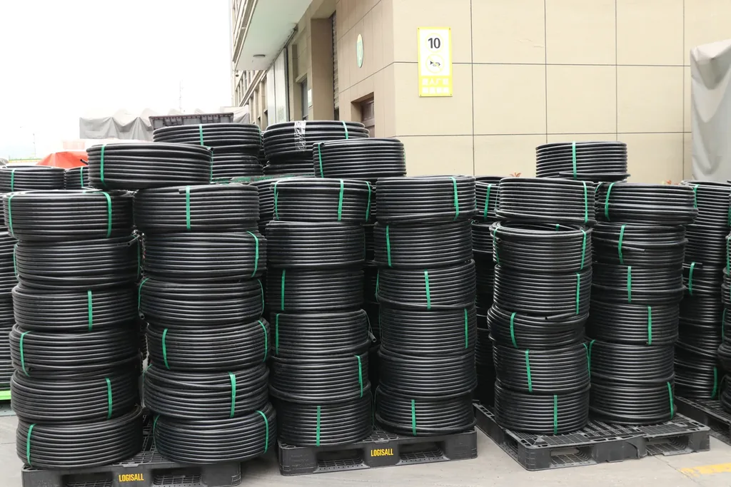
The lowest pressures normally occur at or near the top of the vertical downpipe. Designers commonly hold minimum pressures above −8.0 m of water column, although EN 12056-3 clause 6.2.6 sets no specific limit itself.
The reason for the margin is what waits below it: at about −10.2 m of water column, water reaches its vapour pressure and boils inside the pipe. The vapour cavities then collapse, and collapsing cavities generate impact pressures capable of damaging even stainless steel. On buildings above roughly 14 m, that gap between working pressure and vapour pressure is where the design lives.
Wall class is the specification, not the material name
HDPE, UPVC and cast iron have all been used successfully in siphonic systems. Naming the material is not the same as qualifying it. One published EN 1519 HDPE siphonic range makes the point precisely: it is rated to a minimum pressure of −800 mbar in SDR 26 and −450 mbar in SDR 33, at 20 °C, and those ratings are stated as valid only for rainwater drainage under negative pressure. Convert them and the design decision makes itself.
| Wall class | Rated minimum pressure | As water column | Clears a −8.0 m design floor? |
|---|---|---|---|
| SDR 26 (thicker wall) | −800 mbar | −8.15 m | Yes, with little margin |
| SDR 33 (thinner wall) | −450 mbar | −4.59 m | No |
Two pipes, same material, same standard, same manufacturer — and one of them is disqualified by the wall thickness alone. This is the single most useful thing a buyer can take from this page: on a siphonic enquiry, the negative-pressure rating and the SDR are the specification. If you are new to reading wall classes, our explainer on how SDR, PN and wall thickness relate on HDPE pipe covers how the ratio works and how to write it into a purchase order.
Why ordinary drainage stock is the wrong shelf
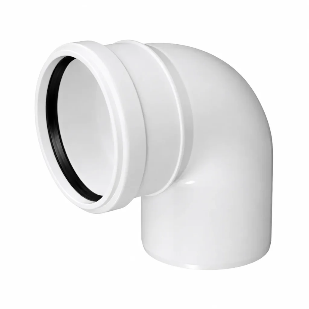
Standard building drainage pipe — the EN 1451 polypropylene and EN 1329 UPVC soil-and-waste ranges — is designed for gravity service at atmospheric pressure with ring-seal push-fit joints. Nothing about that stock is qualified for sustained suction, and the joints in particular are made to resist a head of water pushing out, not a vacuum pulling air in.
The outlets are a separate matter again: siphonic roof drains are built and tested to product standards such as EN 1253 and ASME A112.6.9, with anti-vortex covers and leaf gratings, and an outlet that has not been tested as part of the system is not interchangeable with one that has.
What to check before you accept a siphonic pipe submittal
This is the documentary check, and it is deliberately short because only four things decide it. A submittal that cannot answer all four is not a siphonic submittal, whatever the covering letter says.
- A stated negative-pressure rating, in numbers. Not “suitable for siphonic systems” — an actual minimum pressure in mbar or metres of water column. A datasheet that gives only a positive pressure class is answering a different question.
- That rating tied to a specific SDR. The rating belongs to the wall class, not to the product family. The same range can pass in one SDR and fail in another, as the table above shows.
- The temperature it was established at. Published negative-pressure figures are typically stated at 20 °C; a rating quoted with no temperature is incomplete.
- The product standard, with its edition. EN 1519 for PE pipework inside buildings, EN 1253 or ASME A112.6.9 for the outlets. A bare standard number with no year is the most common way an out-of-date submittal passes review.
What this page will not tell you: we do not publish a negative-pressure rating for our own drainage range, because we do not have one on record. Ask any supplier, including us, for that figure in writing before you specify.
Specifying gravity drainage instead?
If your project is taking the conventional route — and most roofs should — our PP drainage and soil system is built to EN 1451-1 in DN50–200, in two wall classes: TYPE1 at s = 3–3.9 mm for main soil stacks and hot-waste risers, TYPE2 at s = 1.8–3.2 mm for lighter waste branches. This is gravity soil-and-waste stock, not siphonic pipe; we would rather say so here than after your order. For distributors and specifiers sizing gravity drainage runs — if you need a siphonic system, your route is a licensed siphonic designer who will size and guarantee the whole circuit.
Which standard governs what, and what changed in 2025
A recurring source of confusion in tender documents is the assumption that EN 12056-3 tells you how to size a siphonic system. It does not. The standard sets out detailed calculation procedures for conventional roof drainage, and for siphonic systems it gives performance requirements only — no sizing method, because real siphonic design is an iterative pipe-network solution done in proprietary software.
In the UK, EN 12056-3 also carries Approved Document status under Part H of the Building Regulations, which is why its clauses turn up in specifications so often.
Those performance clauses are worth citing individually, because each one corresponds to a failure mode described earlier on this page rather than to a paperwork requirement.
| Clause (EN 12056-3) | What it constrains | The failure it prevents |
|---|---|---|
| 6.2.1 | Same rainfall criteria as conventional; no storage credit | Undersizing by counting storage already consumed |
| 6.2.3 | Priming time | A system that primes too late for a short storm |
| 6.2.4 | Balanced head losses between outlets | Air ingestion at an over-capacity outlet |
| 6.2.6 | Negative pressures (no numeric limit given) | Cavitation damage and wall collapse |
| 6.2.7 | Minimum self-cleansing velocity | Silt build-up between rare priming events |
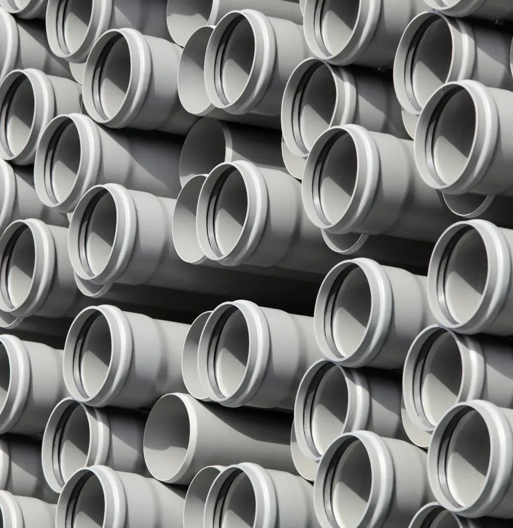
The siphonic-specific guidance lives in BS 8490, and this is where a lot of live specifications are now out of date. BS 8490:2025 was published on 28 February 2025 and supersedes BS 8490:2007. If your standard reference schedule, your NBS clause or your supplier’s submittal still cites the 2007 edition, it is citing a withdrawn document.
Published commentary on the reissue describes secondary drainage being made mandatory where a blockage in an internal gutter could cause water ingress, alongside updated design parameters and firmer handover testing. We have not seen the clause text, so treat that as the direction of travel and buy the standard before you write a number from it into a specification.
Worth noting that the same EN 12056 family governs the drainage inside the building too — if you are sizing the soil and waste side of the same project, our guide to soil pipe system stack sizing under EN 12056 covers Part 2 the way this page covers Part 3.
Best for, and not for: choosing between siphonic and gravity
Siphonic drainage is a specialist answer to a specific geometry problem: a large roof area where the cost of getting many pipes down through the building is high. The design manual for the standard is blunt about the other end of the range, stating that siphonic systems are not usually appropriate for use on domestic buildings. Between those poles, the decision is fairly mechanical.
Work through it in order
- Is the roof large and substantially flat? If not, stop — the head and catchment that make siphonic work are absent, and you are buying complexity.
- Do internal downpipes actually cost you something? Racking layout, clear-span requirements, below-slab drainage runs, column grid. If a dozen gravity stacks are architecturally free, gravity is the lower-risk answer and usually the cheaper one.
- Is the building tall enough to matter, and not so tall that pressure becomes the binding constraint? Above roughly 14 m the cavitation margin needs explicit attention in the design.
- Will anyone be allowed to modify the pipework later? If the building will be fitted out, subdivided or re-serviced by contractors who have never heard of hydraulic balance, weigh that honestly. This is where siphonic systems fail years after handover.
- Is there an internal gutter where a blockage means water inside the building? Plan for a secondary or emergency system, and check the current BS 8490 edition on where it is now required rather than optional.
- Can the site drainage take a concentrated discharge? A primed system delivers the whole roof to one point, and surcharging downstream comes straight back up.
One practical note on procurement, because it catches distributors out. A siphonic system is sold and warranted as a designed circuit — outlets, pipe, fittings, brackets and the calculation behind them. You cannot assemble one from a pipe schedule and a box of drains, and a pipe supplier who tells you otherwise is selling you a liability.
Where a pipe manufacturer is genuinely useful on a siphonic project is the wall class question and the thermal movement the bracket system has to absorb; the hydraulics belong to the system designer.
Conclusion
Siphonic roof drainage is not a bigger version of gravity drainage, and the popular framing of it as a diameter saving hides both what it is good at and where it breaks.
It converts building height into driving head, which lets one stack do the work of twenty, and it pays for that with a narrow operating envelope: it only primes above about 60 percent of capacity, it has almost no reserve above the design storm, and its balance can be destroyed by an undocumented change to the pipework.
If you are weighing the two systems for a large roof, the useful next steps are to fix your design rainfall intensity from the local authority rather than from any article, and to confirm the negative-pressure rating and wall class of whatever pipe is being proposed. If your project is taking the conventional route, you can review our gravity drainage wall classes and sizes and bring us the duty you need to cover.
Frequently Asked Questions
Does a siphonic system work in light rain?
No. Below roughly 60 percent of its full-bore capacity it behaves like a conventional gravity system with a free water surface. That is normal and expected, not a fault.
Can I use standard PP or UPVC drainage pipe for a siphonic system?
Not from ordinary EN 1451 or EN 1329 soil-and-waste stock. Siphonic pipe must be rated for sustained negative pressure, and that rating depends on wall class, not just on the material name.
Which standard should I cite for siphonic roof drainage?
BS 8490:2025 for siphonic-specific guidance, published 28 February 2025 in place of the 2007 edition, alongside BS EN 12056-3 for rainfall and roof drainage performance requirements.
Why can a siphonic pipe be smaller than a gravity pipe?
Because a gravity stack is deliberately sized to run about a third full so it never siphons, while a siphonic pipe runs completely full. The same DN110 carries roughly 2.8 times more flow.
Can a contractor re-route siphonic pipework on site?
Not without a redesign. The head losses from every outlet to the discharge point are balanced by calculation, and an unrecorded change can stop the system priming at all.
Is siphonic drainage suitable for houses?
Generally no. The design manual for EN 12056-3 states siphonic systems are not usually appropriate for domestic buildings, which lack the roof area and the pipe-routing cost that justify them.