Key Takeaways
- Size the main on velocity first. USDA NRCS Conservation Practice Standard 430 caps full-pipe design velocity at 5 ft/s (1.5 m/s) where valves or flow controls sit in or at the end of the line — that single number decides the diameter before friction loss enters the picture.
- SDR and PN are not the same thing, and the PE grade changes the answer. PE100 at SDR11 is PN16; PE80 at the identical SDR11 is only PN12.5, because PE100 has an MRS of 10.0 MPa against 8.0 MPa for PE80.
- The famous “20% pressure rule” is a derived figure, not a primary one. The design rule is 10% emitter discharge variation; with a flow exponent of 0.5 that becomes roughly 20% head variation, split about 55% lateral / 45% manifold.
- Design on aged pipe, not new pipe. Hazen-Williams C = 150 for new PE, around 140 as the aged design value. In the worked example below, that difference alone costs 0.77 m of head.
- ISO 14236 is withdrawn. Compression fittings for PE pressure pipe now sit under ISO 17885:2021, whose scope names irrigation as an application area. A spec sheet still citing ISO 14236 in 2026 has not been reviewed in years.
- For field repair, the Plastics Pipe Institute sets the threshold at a 2-inch hole: at or below that, an electrofusion patch can be permanent; above it, use a full-circle band clamp or cut in a spool piece.
- Mechanical compression fittings need no power, no fusion machine and no open flame — which is why they win on farms 40 km from the nearest generator, and why the range runs 20–110 mm with saddle clamps from 25×1/2 inch to 315×6 inch.
An HDPE pipe irrigation network fails in one of two ways, and they look nothing alike. Either the far end of the block runs dry because somebody sized the main on a price list instead of a flow rate, or a tractor wheel finds a shallow lateral in week three and the whole shift shuts down while a repair crew waits for a fusion machine to arrive from town.
This page walks one network end to end — a 12-hectare drip block, four shifts, 60 m³/h at the pump — and shows the arithmetic at each step. Then it covers the part nobody plans for: what you actually do when the pipe is already in the ground and already damaged. Every design number here is either traceable to a published standard or worked out in front of you from one, so you can check it rather than take it on faith.
The design brief: what we are sizing
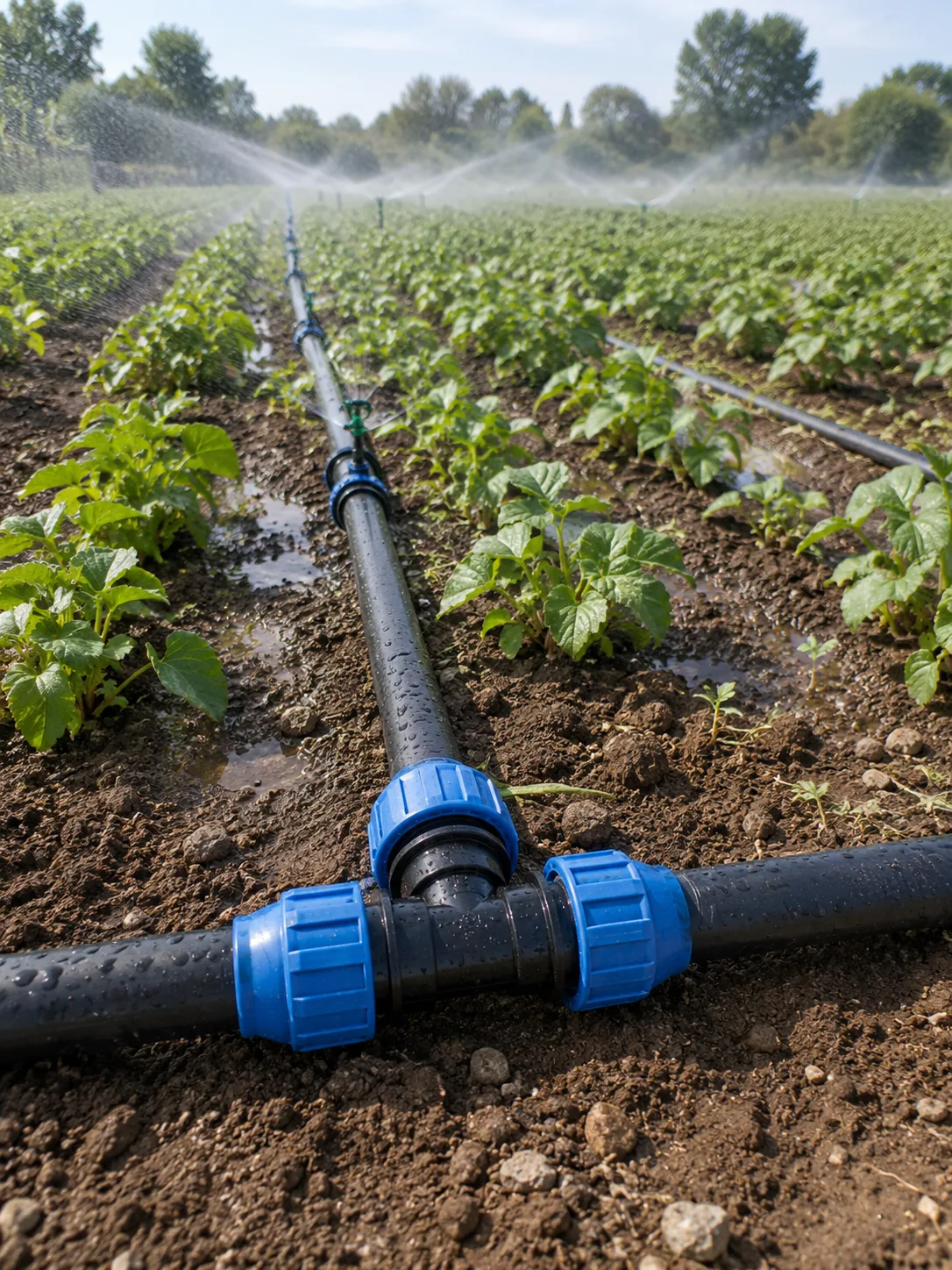
Here is the block. A 12-hectare citrus planting, drip irrigated, on ground that rises about 3 m from the pump to the far corner. Tree rows sit 4 m apart, so laterals run at 4 m spacing, with 4 l/h inline drippers at 0.5 m spacing along each lateral. The grower runs four shifts of 3 ha, which is normal practice — irrigating all 12 ha at once would need a pump and a main nobody wants to pay for.
The mainline from the pump to the head of the furthest block measures 420 m. Most quick estimates get that number wrong, because people measure the straight line on a map rather than the route the trencher takes around the packing shed.
| Design input | Value | Why it matters |
|---|---|---|
| Total area | 12 ha, run as 4 shifts of 3 ha | Shift size sets peak flow, not total area |
| Emitter | 4 l/h, 0.5 m spacing | Multiplied by emitter count to give block flow |
| Lateral spacing | 4 m (tree rows) | Sets emitters per hectare with the 0.5 m spacing |
| Mainline length | 420 m, pump to furthest block head | Friction loss scales directly with length |
| Elevation rise | 3 m, pump to far corner | Costs 3 m of head, about 0.3 bar |
Step 1 — Turn emitters into a flow rate
Everything downstream depends on getting this one number right, and it is pure counting. Each emitter occupies a rectangle of ground 0.5 m along the lateral by 4 m between laterals — 2 m² per emitter. A hectare is 10,000 m², so the block carries 5,000 emitters per hectare.
At 4 l/h each, that is 20,000 l/h per hectare, or 20 m³/h per hectare. Run three hectares at once and the network has to deliver 60 m³/h, which is 16.7 l/s or 0.0167 m³/s. Hold onto the cubic-metres-per-second figure — every hydraulic formula from here on wants SI units, and mixing l/h into a friction equation is the single most common arithmetic failure in irrigation design.
Design for the shift, not the farm. Sizing this main for all 12 ha would demand 240 m³/h and roughly double the pipe diameter — for a network that never runs that way.
Step 2 — Size the main on velocity, not habit
Most sizing guides jump to friction loss here. That is backwards. Friction loss costs you energy, which is money; excessive velocity costs you the pipeline, which is the whole asset. The USDA NRCS Conservation Practice Standard 430 for irrigation pipelines is direct about it: do not exceed 5 feet per second — 1.5 m/s — full-pipe flow velocity at design capacity in pipelines that have valves or other flow control appurtenances within the line or at the downstream end.
Every irrigation network has valves at the downstream end — that is what a block valve is — so the cap applies to essentially every design of this type. It exists because of what happens when a valve shuts. Moving water has momentum, and stopping it quickly converts that momentum into a pressure spike travelling back up the pipe: water hammer. The faster the water was moving, the bigger the spike, and the spike does not care that your pipe is rated PN10 under steady conditions.
Working the diameter backwards from velocity
Flow equals area times velocity. Rearranged for the minimum internal area at the velocity cap: A = Q / v = 0.0167 / 1.5 = 0.0111 m². Convert that area to a diameter and you get 118.9 mm minimum internal bore. Note that word — internal. HDPE pipe is specified by outside diameter, and the wall thickness you choose eats into the bore. This is where designs go wrong.
| Pipe (OD × SDR) | Wall | Internal bore | Velocity at 60 m³/h |
|---|---|---|---|
| 110 × SDR17 | 6.5 mm | 97.1 mm | 2.25 m/s — fails |
| 125 × SDR17 | 7.4 mm | 110.3 mm | 1.74 m/s — fails |
| 140 × SDR11 | 12.7 mm | 114.5 mm | 1.62 m/s — fails |
| 140 × SDR17 | 8.2 mm | 123.5 mm | 1.39 m/s — passes |
| 160 × SDR17 | 9.4 mm | 141.2 mm | 1.06 m/s — passes, oversized |
Look at the two 140 mm rows. Same outside diameter, same trench, same fittings on the shelf — and one passes the velocity check while the other fails it. The thicker SDR11 wall pulls the bore down to 114.5 mm, below the 118.9 mm the flow needs, and pushes velocity to 1.62 m/s. A buyer who “upgraded” to the heavier wall thinking more plastic means more safety has quietly created a water hammer exposure. 140 × SDR17 is the answer here, and 160 mm is real money wasted on a duty that never arrives.
Step 3 — Pick SDR and PE grade for the pressure class
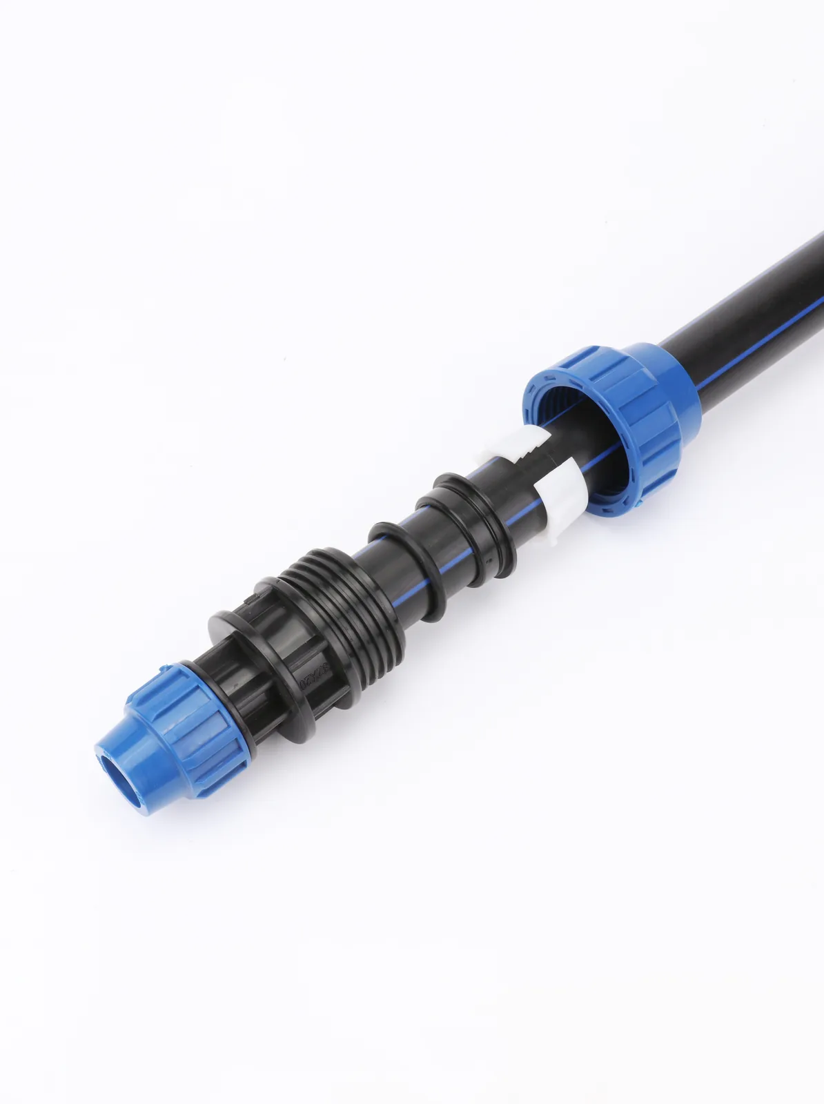
SDR — standard dimension ratio — is outside diameter divided by wall thickness. A lower SDR means a thicker wall relative to the pipe size, and a higher pressure rating. That relationship is not a lookup table somebody invented; it comes out of a formula in the ISO 4427 family:
P = (20 × MRS) / [C × (SDR − 1)], giving pressure in bar. C is the design coefficient — minimum 1.25 for water.
MRS is minimum required strength, and it is where the PE grade enters. PE100 has an MRS of 10.0 MPa; PE80 has 8.0 MPa. Feed both through the formula at SDR11 and PE100 lands on PN16 while PE80 lands on PN12.5 — the same wall thickness, a 25% difference in what the pipe will hold. This is why “SDR11 pipe” on a purchase order is an incomplete specification. Without the grade beside it, the pressure class is undefined.
| SDR | PE100 (MRS 10.0) | Typical irrigation use |
|---|---|---|
| SDR11 | PN16 | Pump discharge, steep terrain, long rising mains |
| SDR17 | PN10 | Standard buried mains and submains — the workhorse |
| SDR21 | PN8 | Low-head gravity distribution |
| SDR26 | PN6 | Submains and laterals at low pressure only |
For our block, PE100 SDR17 gives PN10 — a 10 bar pipe on a system whose working pressure will land near 2 bar. That is not overkill. The margin absorbs the surge the velocity cap is already limiting, plus whatever the pump does on an uncontrolled start. Match the fittings to it: our PN10 compression fitting range against a PN10 pipe gives one coherent pressure class across the network, with no weak link hiding at a joint.
Step 4 — Friction loss, and which C factor to use
With the diameter fixed at 140 × SDR17, friction loss over the 420 m main comes from the Hazen-Williams equation in metric form:
hf = 10.67 × L × Q1.852 / (C1.852 × d4.87) — with hf in metres of head, L in metres, Q in m³/s and d in metres.
That d4.87 term is why diameter decisions dominate everything else. Bore appears to nearly the fifth power, so a small increase in diameter collapses the friction loss. Drop from 140 mm to 110 mm on this same duty and head loss goes from 6.41 m to 20.74 m — a substantially bigger pump to push water through cheaper pipe, plus the electricity bill for it every season.
C = 150 is a marketing number
The C factor describes how smooth the pipe is. For new PE and HDPE the published value is C = 150, and that figure appears on nearly every supplier datasheet, because it makes the pipe look good. Aged pipe is a different story: C = 140 is the commonly used aged design value and C = 130 represents genuinely aged pipe. Conservative practice is to design on the aged value.
Run our main both ways. At C = 150 the 420 m of 140 × SDR17 loses 5.64 m of head. At C = 140 it loses 6.41 m. The gap is 0.77 m — under a tenth of a bar, and easy to dismiss. It is also roughly a third of the total head variation the emitters will tolerate across the whole subunit, which we are about to calculate. Designers who spend that margin on optimistic pipe roughness have nothing left when the pump wears or a filter starts to load up.
Small laterals are rougher than mains
There is a second correction almost nobody applies. Measured C values for small-diameter polyethylene tubing, published in the ASCE Journal of Transportation Engineering, come in well under 150: 129 at 13 mm, 136 at 16 mm, 144 at 19 mm and 148 at 22 mm. A 16 mm drip lateral is not a 150 pipe. Using the mains value on your laterals underestimates lateral loss, and lateral loss is what drives emitter uniformity at the row scale.
Step 5 — The pressure budget and the 20% myth
Search for drip design rules and you will be told, repeatedly and without explanation, that pressure must not vary by more than 20% across a block. The number is roughly right. The reasoning is almost always missing, and without it you cannot tell when the rule stops applying.
The actual design rule, per ASABE EP405, is that emitter discharge variation within a subunit should not exceed 10% of nominal discharge. Discharge is what grows the crop; pressure is only the means. For a standard turbulent-flow emitter the flow exponent is about 0.5, so discharge tracks the square root of head. Invert it: to hold discharge within 10%, head may vary by 1.10² = 1.21, so about 21%. Round to 20% and you have the rule everyone repeats.
Now the part that matters operationally. That exponent is emitter-specific. A pressure-compensating emitter has a much lower exponent, which is the whole point of buying one — it holds discharge steady across a wider pressure band, so the 20% head rule is needlessly tight for it. Repeat the rule without knowing the exponent and you will either over-engineer a PC system or under-engineer a non-PC one.
Splitting the budget
Take a 4 l/h emitter with a 10 m nominal operating head — 1 bar. Allowable head variation across the subunit is 20% of that: 2.0 m total, split roughly 55% lateral and 45% manifold, so 1.1 m for the lateral run and 0.9 m for the manifold. Those are the numbers your lateral length and manifold diameter have to satisfy, and they are small. It is why drip laterals get shorter as slope increases, and why a “just add another 30 m to that row” request from the field is a design change, not a favour.
Elevation eats the budget without asking. Ten metres of elevation equals about 1 bar, so a 2.3-foot rise costs 1 psi. Our block rises 3 m from pump to far corner — 3 m of head, about 0.3 bar. Run a subunit up that slope and the elevation change alone consumes more than the entire 2.0 m allowance. The fix is to lay subunits across the contour rather than up it, or to use pressure-compensating emitters and accept the higher unit cost.
Two more line items belong in the budget before you size the pump. Small pressure regulators typically cost around 5 psi of loss, and emitter manufacturing scatter is real: select emitters with a manufacturer’s coefficient of variation below 3%. At 3% CV, 95% of a 1 gph emitter population discharges between 0.94 and 1.06 gph — which is variation you get before a single metre of pipe has been laid, and it comes straight out of the same 10% discharge allowance.
The block, totalled
| Component | Head | Source |
|---|---|---|
| Emitter operating head | 10.0 m | Emitter nominal rating |
| Mainline friction, 420 m | 6.41 m | Hazen-Williams at C = 140 |
| Static lift | 3.0 m | Surveyed elevation rise |
| Subunit allowance | 2.0 m | 20% of nominal head, per the 10% discharge rule |
| Filtration, valves, regulators | Site-specific | Take from the equipment supplier’s curves, clean to dirty |
That last row is deliberately not a number. Filter loss depends on the filter type, the water quality and how dirty you let it get before backwashing, and any figure quoted without those three things is decoration. Get it from the curves your filtration supplier publishes, at the dirty end, not the clean end.
Field repair: three methods and when each applies
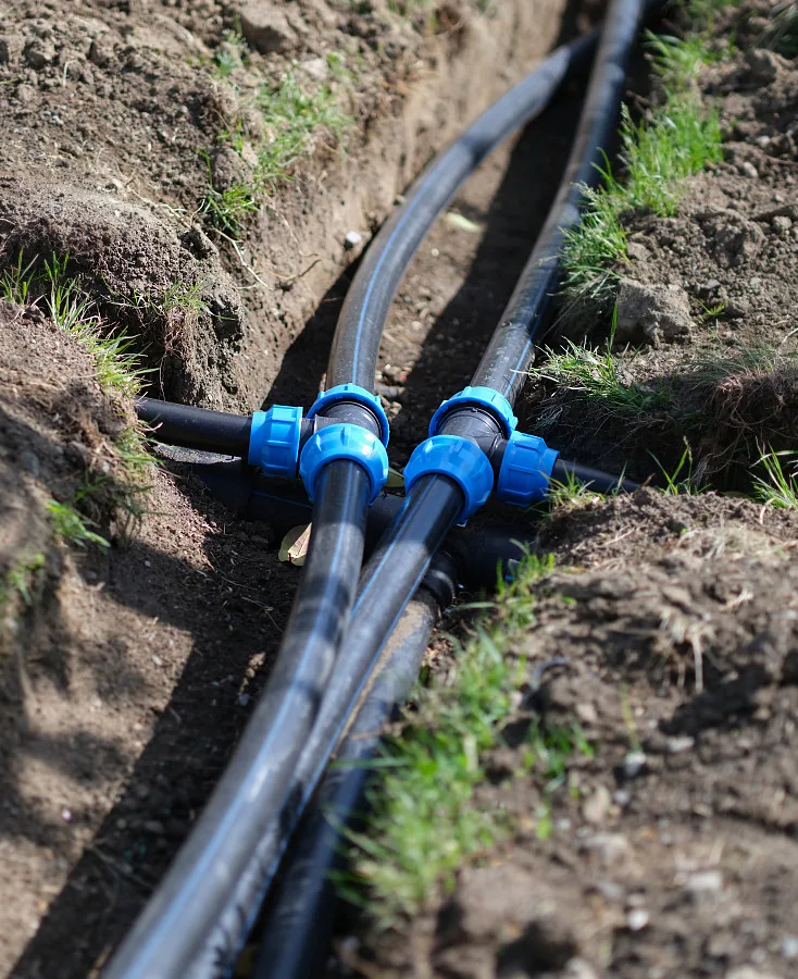
Sizing is a desk exercise you do once. Repair is a field exercise you do every season, usually in the wrong weather, often 40 km from the nearest three-phase supply. The Plastics Pipe Institute sets a size threshold worth memorising: for local damage of a hole 2 inches or smaller, an electrofusion patch may be used as a permanent repair. Above that, PPI recommends mechanical full-circle band clamps, or replacing the damaged length with a spool piece. Which repair method your line can take was fixed by how it was jointed when it was laid, and the selection criteria sit in our HDPE pipe jointing methods comparison.
The constrained-pipe problem
Here is the detail that catches crews out. A buried, backfilled pipe is constrained — it cannot be pulled apart lengthwise to slide a coupling on, because the soil holds it. PPI notes that constrained pipe may require fittings that need no longitudinal movement, such as spool assemblies with electrofusion couplings. Plan the repair around whether the pipe can move, not just around the size of the hole. Crews who skip that assessment end up excavating another 6 m of trench in each direction to get the slack they need.
Why compression wins on a farm
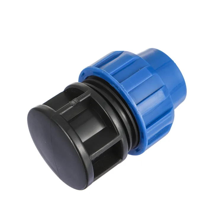
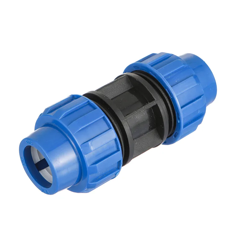
Electrofusion needs a controller, a generator and a clean, scraped, dry pipe surface. On a municipal job that is all normal. On a citrus block in August, with a shift to finish, it is a half-day round trip. Mechanical compression couplings need no fusion machine, no controller and no open flame — a restrained type uses an internal stiffener and a grip ring, and goes together with hand tools. That is why compression dominates agricultural HDPE despite fusion being technically the superior joint.
| Situation | Method | Needs power on site? |
|---|---|---|
| Hole 2 inches or smaller, pipe accessible | Electrofusion patch, permanent | Yes — controller and generator |
| Hole larger than 2 inches | Full-circle band clamp, or cut in a spool piece | Clamp no; spool depends on joint type |
| Clean break, pipe can be pulled apart | Compression coupling, 20–110 mm range | No — hand tools only |
| Constrained buried pipe, no slack | Spool with electrofusion couplings | Yes |
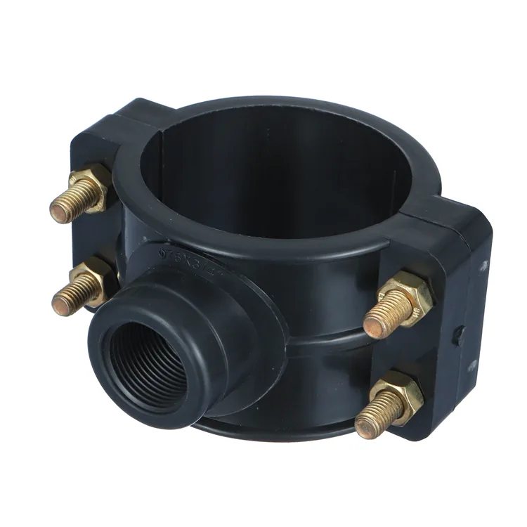
| New lateral off a live main | Saddle clamp, 25×1/2 inch to 315×6 inch | No — bolt-on |
Tapping a live main
Adding a lateral to an existing main does not need the main cut. A saddle clamp bolts around the pipe, seals against the outside wall, and gives you a threaded outlet to drill through. Our range covers 25×1/2 inch through to 315×6 inch in single and double saddle configurations. Torque the bolts evenly in a cross pattern — uneven torque distorts the seal seat and produces a weep that only appears once the block is up to pressure and everyone has gone home.
Which standards actually apply in 2026
Most HDPE irrigation pages on the web are quietly out of date, and a distributor who repeats their standards list in a tender document inherits the error. The big one: ISO 14236, the old standard for mechanical-joint compression fittings on PE pressure pipes, has been withdrawn. It was superseded by ISO 17885, whose first edition replaced ISO 10838-1:2000, ISO 10838-2:2000, ISO 10838-3:2001 and ISO 14236:2000 as a technical revision. The current text is ISO 17885:2021, second edition, published 21 June 2021. Its scope explicitly names supply of water for irrigation as an application area, alongside gas, water for human consumption, pressure drainage and industrial applications. Flanges, indoor hot and cold water, and district heating sit outside it.
If a supplier’s compression fitting datasheet still says “manufactured to ISO 14236” in 2026, that is not necessarily a bad fitting. It is a document nobody has reviewed in several years. Ask when the type testing was last done and against which edition — the answer tells you more about the supplier’s quality system than the certificate scan does.
Editions, not just numbers
The pipe standards have moved too, and citing the bare number without the edition is how obsolete requirements survive in specifications:
| Standard | Current status | Covers |
|---|---|---|
| ISO 4427-1 | 2019 edition | General requirements for PE water and pressure sewerage |
| ISO 4427-2 | 2019, 2nd ed. + Amd 1:2023 | PE pipes, up to 25 bar MOP at 20 °C |
| EN 12201-2 | 2024 edition, released 14 March 2024 | PE pipes for water supply, drains and sewers under pressure |
| ISO 17885 | 2021, 2nd ed. — replaces ISO 14236 | Mechanical fittings, irrigation named in scope |
| ISO 14236 | Withdrawn | Do not cite in new specifications |
ISO 4427-2:2019 plus its 2023 amendment is the live text for the pipe itself, and a revision is under committee development — worth watching, not worth waiting for. The EN 12201-2:2024 revision is recent enough that most competitor pages still quote the 2011 edition. Bekaatherm HDPE pipe is produced to ISO 4427, EN 12201 and DIN 8074 / 8075, under a company holding SKZ (Germany), ISO, CE and WRAS certification. Which schedules and scopes apply to a given product line varies, so request the current certification pack and check the scope against your tender wording rather than assuming a company-level mark covers every item on the packing list.
One hedge worth stating plainly: approval scopes, national annexes and local water-authority requirements vary by market and by product type. Confirm what your destination market accepts with the relevant authority or your certification consultant before committing a specification to a tender.
Best for / not for: compression fittings
Compression fittings are not universally right, and a supplier who tells you they are is selling rather than advising. Where the line falls:
Best for
- Small to mid diameters. The 20–110 mm band is where the mechanical joint is quick, cheap and reliable. The legacy standard capped compression fittings at 160 mm outside diameter and 40 °C, which tells you where the technology naturally stops.
- Sites with no power. No generator, no controller, no fusion machine. A crew with spanners can complete a joint.
- Networks that get reconfigured. Seasonal crop rotation means moving submains. A mechanical joint comes apart and goes back together; a fused joint is a cut.
- Repairs under time pressure. A leaking block during peak demand is a same-hour problem, not a same-week one.
- Distributor stock. Compression fittings sell to farmers walking into a counter. Fusion fittings need a trained installer attached.
Not for
- Large-diameter trunk mains. Above the compression range you are into butt fusion or electrofusion, and that is the correct answer, not a compromise.
- High-pressure duties beyond the fitting class. A PN10 fitting on a PN16 pipe gives you a PN10 network. The joint sets the class, and the pipe marking will not warn you.
- Gas. Different standard scope, different approval regime, different fitting entirely.
- Constrained buried pipe with no slack. If the line cannot be pulled apart lengthwise, a coupling that needs longitudinal movement is the wrong tool — this is exactly the case PPI flags for electrofusion spool assemblies.
From spec sheet to container: what to specify
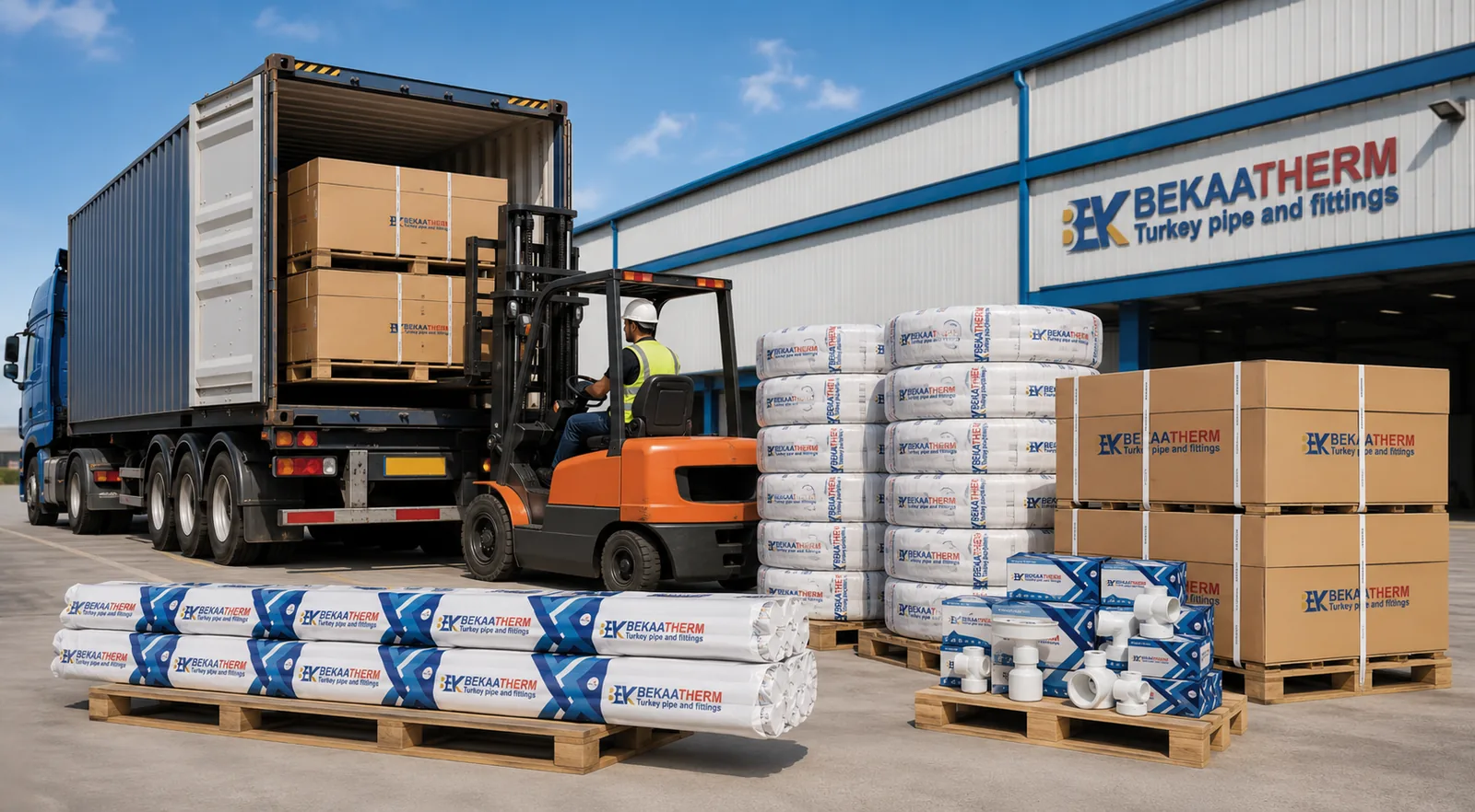
The design work above produces a specification. Turning it into a landed container needs six more lines on the purchase order, and leaving any of them blank is how the wrong goods arrive with correct paperwork.
- Outside diameter and SDR, together. “140 mm PN10” is ambiguous until the grade is named, because PN10 comes from SDR17 in PE100 and from a different SDR in PE80.
- PE grade. PE100 or PE80. It changes the pressure class at identical wall thickness.
- Standard and edition. ISO 4427-2:2019 + Amd 1:2023, or EN 12201-2:2024. Not the bare number.
- Colour and stripe. Black with a blue stripe reads as potable water in many markets; irrigation conventions differ by country. Confirm before the extruder starts.
- Fitting pressure class. Match it to the pipe. Our compression range is PN10 throughout.
- Certificate pack. Name which certificates you need with the shipment, before production rather than after.
Order quantities and terms
These are our published commercial parameters. Minimum order is one 20GP mixed container of pipe, fittings and valves for a trial, or 500 kg per size and colour for a single specification. Regular in-production sizes ship in 15–25 days; private-label runs take 30–45 days. Payment is 30% T/T deposit with 70% against copy B/L, and an irrevocable L/C at sight is accepted from USD 50,000. Trade terms default to FOB İstanbul or Mersin, with CFR and CIF on request.
Be careful with container figures. A 20GP gives roughly 33 m³ usable against a ~28 tonne payload; a 40HQ gives roughly 76 m³. Coiled HDPE is bulky, and its density on the floor depends on coil diameter and how tightly the coils nest, so quantity per container has to be calculated for your actual size mix rather than copied from a pipe of a different type. Ask for the loading plan with the quotation. Our walkthrough of FOB pricing and container loading covers the method, and the PN20 vs PN25 pressure rating piece applies the same pressure-class logic to a different product family.
How we handle origin and documents
Worth stating plainly, because it affects your customs paperwork. We supply from two origins — Türkiye and a Chinese partner plant — with origin allocated by market. Your order’s origin is confirmed in writing on the proforma invoice before you pay a deposit, and the certificate of origin, packing list and bill of lading are issued consistently with it. If your market has origin-sensitive duty treatment, raise it at the enquiry stage.
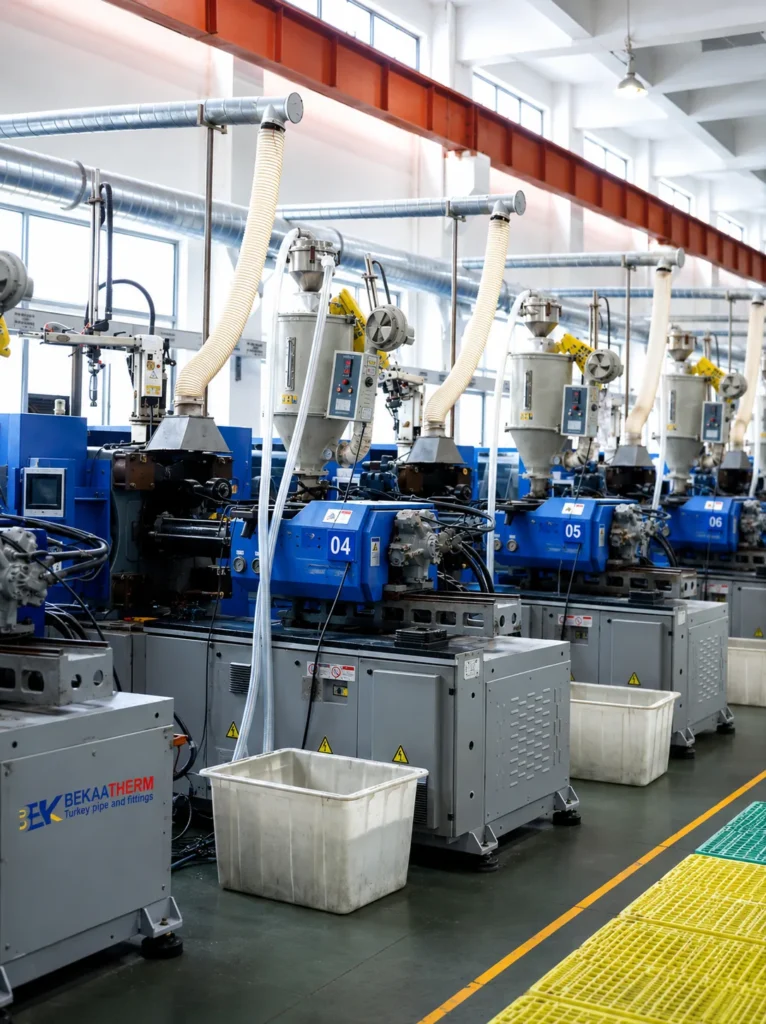
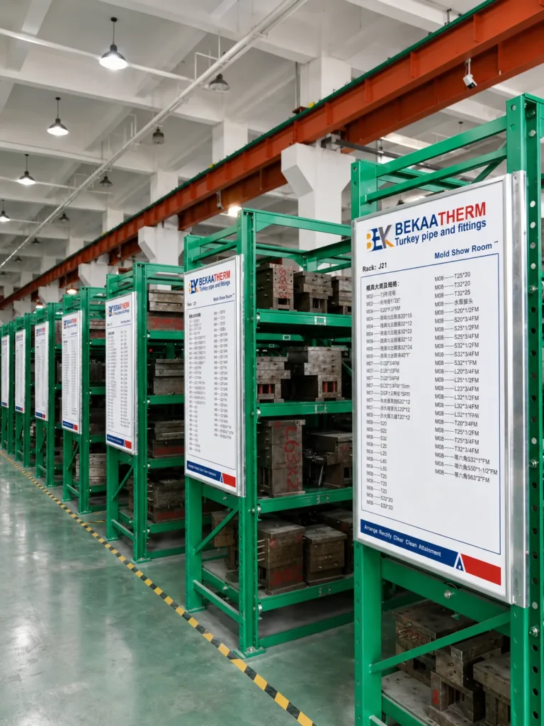
Products carry a 50-year warranty against material and manufacturing defects, backed by 30 years of manufacturing across a 120,000 m² site with 1000+ staff and 10,000 moulds, shipping to 118+ countries. For the classification side, rigid polyethylene pipe generally falls under HS 3917.21, with plastic pipe fittings under HS 3917.40 — though duty rates are destination-specific, so confirm the applicable rate with your customs broker rather than working from a supplier’s estimate.
Conclusion
The whole design collapses to a short sequence: count the emitters to get flow, size the diameter so velocity stays under 1.5 m/s, choose SDR against the PE grade to land the pressure class, then check friction loss on an aged C value rather than a new-pipe one. The uniformity budget — 10% discharge, roughly 20% head, split 55/45 — is what tells you whether the design survives contact with a sloping field.
Then plan the repairs before you need them. Stock compression couplings and saddle clamps in the sizes your network actually uses, because the method that needs no power is the one that gets used at 6 a.m. in August. If you are pricing a network now, work out your diameter and pressure class from the steps above first — a supplier conversation goes very differently when you arrive with a specification instead of a request for a catalogue.
Frequently Asked Questions
What size HDPE pipe do I need for 60 m³/h of irrigation flow?
You need at least 118.9 mm of internal bore to keep velocity at or below 1.5 m/s. In PE100 that means 140 mm outside diameter at SDR17, which gives a 123.5 mm bore and 1.39 m/s. A 140 mm SDR11 pipe fails the same check.
Is ISO 14236 still a valid standard for compression fittings?
No. ISO 14236 has been withdrawn and superseded by ISO 17885, whose current edition is ISO 17885:2021, published 21 June 2021. Its scope explicitly names supply of water for irrigation. Treat a datasheet citing ISO 14236 as unreviewed.
Which Hazen-Williams C factor should I use for HDPE irrigation pipe?
Use 140, the commonly applied aged design value, rather than the 150 quoted for new pipe. For small-diameter laterals go lower still — measured values run 129 at 13 mm and 136 at 16 mm.
Where does the 20% pressure variation rule actually come from?
It is derived, not primary. The design rule is 10% emitter discharge variation within a subunit. For an emitter with a flow exponent of 0.5, holding discharge within 10% allows head to vary by about 21%, conventionally split 55% lateral and 45% manifold.
Can I repair an HDPE irrigation line without a fusion machine?
Yes, with mechanical compression couplings or full-circle band clamps, which need no controller, generator or open flame. The limit is whether the buried pipe has enough slack to be pulled apart lengthwise; constrained pipe may need an electrofusion spool assembly instead.
What is the difference between PE80 and PE100 at the same SDR?
Pressure class. PE100 has a minimum required strength of 10.0 MPa against 8.0 MPa for PE80, so PE100 carries about 25% more pressure at identical wall thickness. PE100 SDR11 is PN16; PE80 SDR11 is PN12.5.
How do I add a new lateral to an existing HDPE main?
Use a saddle clamp, which bolts around the main and gives a threaded outlet without cutting the line. Sizes run from 25×1/2 inch to 315×6 inch in single and double configurations. Torque the bolts in a cross pattern to avoid distorting the seal.
What is the minimum order for HDPE pipe and fittings?
One 20GP mixed container of pipe, fittings and valves for a trial order, or 500 kg per size and colour for a single specification. Regular in-production sizes ship in 15–25 days; private-label runs take 30–45 days.