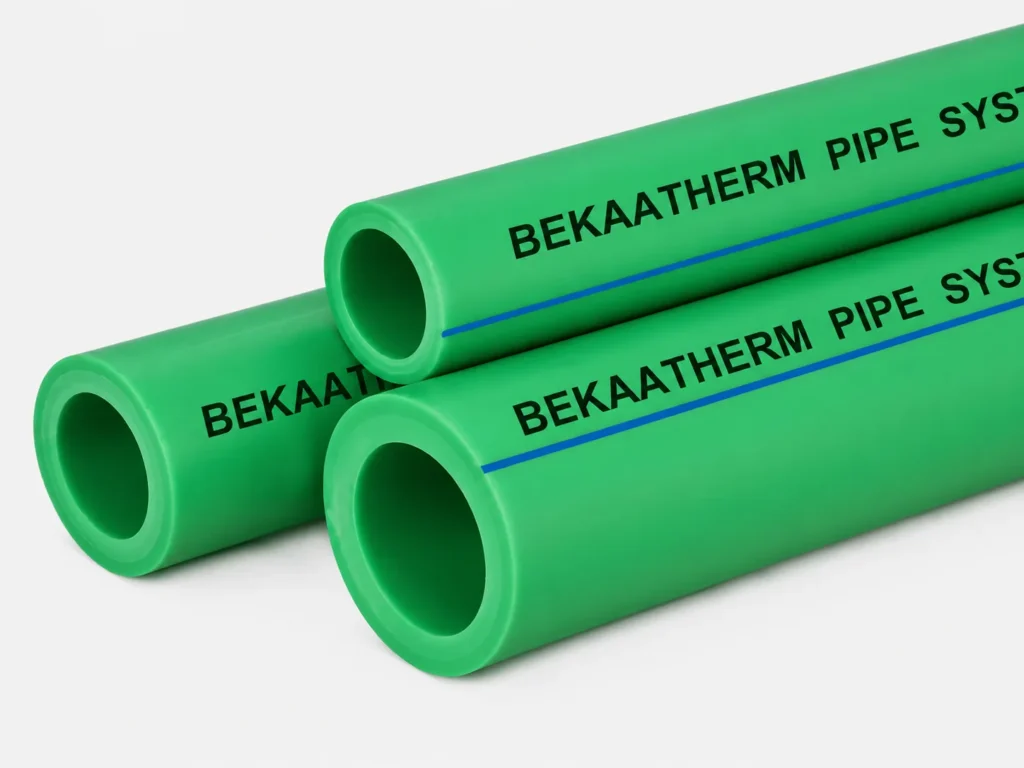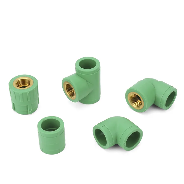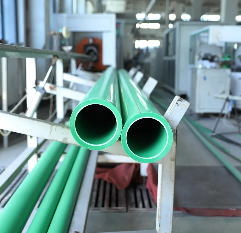
Most questions about PPR pipe for hot water in a heating system are one question in disguise: where in the system does the plastic go? Get that boundary right and PP-R gives you a fused, corrosion-free distribution network with a 50-year design life. Get it wrong — a loop buried in screed, or a leg taken onto a solar collector circuit — and you have built a failure into a floor you cannot open.
One number settles most arguments. Published DIN 8078 operating-condition data for PN25 PP-R shows 32,4 bar at 20 °C for 50 years; at 95 °C the same pipe is listed at 6,5 bar for 5 years. Pressure fell 80%, service life fell 90%. Any page telling you PN25 handles 95 °C for half a century is reading the top row and ignoring the bottom one.
Key takeaways
- PP-R is a distribution material for heating: risers, primaries, manifold tails and radiator drops. The embedded screed loops are a different job for a different pipe.
- Underfloor heating is ISO 10508 Class 4 — 20 °C for 2,5 years, then 40 °C for 20 years, then 60 °C for 25 years. Low-temperature systems fall in Class 3.
- At 70 °C for 50 years, published DIN 8078 data gives PN20 8,5 bar and PN25 10,7 bar. That 2,2 bar step is what PN25 actually buys you on a heating circuit.
- A “95 °C rating” is a short-excursion limit. ISO 10508 allows the malfunction temperature only 100 hours across 50 years.
- Never put any thermoplastic on a solar collector primary loop. ISO 9806:2017 exists partly to tell you why.
- Closed heating loops need an oxygen barrier. DIN 4726 sets it at 0,32 mg/(m²·d) at 40 °C for class 4.
Where PP-R belongs in a heating system
PP-R (polypropylene random copolymer — the green or white pipe joined by socket fusion) is in scope for heating work, and the standard says so plainly. ISO 10508:2006 covers plastics piping used “in transportation systems of hot water for heating, under design pressures up to at least 10 bar.” The question is never whether PP-R is allowed near a heating system. It is which leg.
Three sourced facts decide it. PP-R’s thermal conductivity is 0,23 W/m·K measured to DIN 52612-1, which makes it a poor thin-wall emitter next to the pipe used in screed. Its linear expansion coefficient is 1,5 × 10⁻⁴ K⁻¹ per DIN 53712 — large for something you intend to bury. And it is joined by heat fusion, so an embedded circuit would contain buried joints, while the logic of a floor loop is one unbroken manifold-to-manifold length.
Notice what that list does not say. None of it says PP-R is too weak or too hot-natured for underfloor heating. It says PP-R is the wrong shape for being cast into concrete. The duty itself — 40 °C to 60 °C water in a floor — sits squarely inside what the material handles.
Best for
- Boiler-room and plant-room pipework up to 63 mm, where fused joints beat threaded steel on labour and on leak count.
- Vertical risers and horizontal primaries feeding heating manifolds across a building.
- Manifold tails and radiator drops, including exposed final connections.
- The secondary side of a solar installation, downstream of the cylinder and a tempering valve.
Not for
- Embedded floor or wall loops in screed. Use flexible barrier loop pipe and keep the circuit jointless.
- Any part of a solar collector primary circuit, on either flow or return.
- Steam, or any circuit whose malfunction temperature is not mechanically capped.
- Distribution above 63 mm, which is simply outside our PP-R size range.

This split is not a limitation to apologise for. It is how a good heating installation is normally built, and our own solar and underfloor heating system page is organised on exactly that boundary.
Which ISO 10508 class your system actually is
ISO 10508 classifies service conditions, and those classes are the vocabulary your supplier’s declaration should use. Each class is a duty cycle, not a single temperature — a sequence of temperatures for stated durations adding up to a 50-year life. Underfloor heating is Class 4. Ask which class a pipe is declared for and you learn more from that one answer than from a page of adjectives.
| Class | Design temperature profile (TD) | Tmax | Typical field of application |
|---|---|---|---|
| Class 3 | 20 °C / 0,5 y, then 30 °C / 20 y, then 40 °C / 25 y | 50 °C for 4,5 y (Tmal 65 °C / 100 h) | Low-temperature under-floor heating |
| Class 4 | 20 °C / 2,5 y, then 40 °C / 20 y, then 60 °C / 25 y | 70 °C for 2,5 y (Tmal 100 °C / 100 h) | Under-floor heating and low-temperature radiators |
| Class 5 | 20 °C / 14 y, then 60 °C / 25 y, then 80 °C / 10 y | 90 °C for 1 y (Tmal 100 °C / 100 h) | High temperature radiators |
Service conditions per ISO 10508:2006, Table 1. Each class also carries the 50-year cold-water baseline of 20 °C at 10 bar.
The malfunction temperature is not an operating point
ISO 10508 defines Tmal as the highest temperature reached “when the control limits are exceeded” — when something has gone wrong. The standard’s own note puts a hard budget on it: up to a total of 100 hours over a period of 50 years. That is two working weeks of fault condition across half a century. So a datasheet saying 100 °C is describing a survivable accident, not a design flow temperature. That distinction dismantles most of the “PPR handles 95 °C” marketing you will read. Tmax for Class 4 is 70 °C, and even that is allowed for only 2,5 years of the 50.
When to specify Class 3 instead
Heat pumps changed the arithmetic. A low-temperature floor running 35 °C flow sits comfortably inside Class 3, and European regulation keeps pushing flow temperatures down. Class 3 carries one condition worth reading twice: ISO 10508 permits it “only … when the malfunction temperature cannot rise above 65 °C.” That means a mechanical cap — a thermostatic mixing valve or limiting device — not a setpoint someone can turn up. If the boiler can bypass the mixing group, you are back in Class 4 whatever the paperwork says.
PN20 or PN25: read the derating table
PN is the pressure the pipe holds at 20 °C. Heat it and that number falls, and it falls further the longer you want the pipe to last. Two axes, not one — and almost no competitor publishes both, which is why this debate usually gets settled with adjectives. Below is published DIN 8078 operating-condition data for both classes.
| Water temperature | Service life | PN20 (SDR 6) | PN25 (SDR 5) |
|---|---|---|---|
| 20 °C | 50 years | 25,7 bar | 32,4 bar |
| 40 °C | 50 years | 18,3 bar | 23,1 bar |
| 60 °C | 50 years | 12,9 bar | 16,2 bar |
| 70 °C | 50 years | 8,5 bar | 10,7 bar |
| 80 °C | 25 years | 6,5 bar | 8,1 bar |
| 95 °C | 5 years | 5,2 bar | 6,5 bar |
Published DIN 8078 operating-condition data for PP-R, S=2,5/SDR 6 (PN20) and S=2/SDR 5 (PN25). Note that the service-life column changes with temperature — it is not 50 years all the way down.
Watch the life axis. At 70 °C the same PN20 pipe is listed at 12,9 bar for 1 year, 11,6 bar for 10 years, 10,0 bar for 25 years and 8,5 bar for 50 years. Nothing about the pipe changed — only the years you asked it to survive. A specifier who quotes a bar figure without stating a design life has not finished the calculation.
Our position: PN25 on heating primaries, and it is not close
At 70 °C for 50 years the step from 8,5 to 10,7 bar is a 26% gain in allowable working pressure, for a wall-thickness change and a modest price difference. On a domestic cold or warm water leg, PN20 is honest engineering. On a heating primary that can see 70 °C, PN20 leaves you designing against 8,5 bar in a system that may be static-tested near that figure — the margin you thought you had is the margin temperature already spent. Specify PN25 for heating duty. The size-by-size comparison is in our PN20 vs PN25 pressure rating guide.
Why 50-year design life and this table agree
Our PP-R carries a 50-year warranty against material and manufacturing defects, matched to the 50-year design life at rated pressure and 20 °C under ISO 15874. Read the qualifier: at rated pressure and 20 °C. That is the same corner of the table as the 25,7 and 32,4 bar figures, and ISO 10508 anchors it to a demonstration of 50 years at 20 °C and 10 bar using the ISO 9080 extrapolation method. Warranty and derating table describe the same pipe at two duty points. Anyone quoting the 50-year figure without the temperature qualifier is quoting half a sentence.
Checking a supplier’s PN claim in five minutes
For engineers comparing quotations from more than one PP-R source. Ask for these four things and compare answers side by side:
- The ISO 10508 application class the pipe is declared for, in writing.
- The pressure/temperature/service-life table for the exact SDR being quoted, not a generic brochure page.
- The scope of each certificate — a mark that covers cold water only is not a heating approval.
- Oxygen permeability evidence for anything sold as barrier pipe.
Our own marks are SKZ (Germany), ISO 15874, CE and WRAS, and the scope of each is listed on the certifications page.
Solar: where the plastic stops
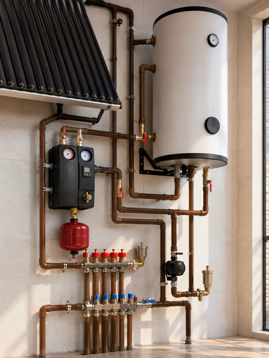
A solar thermal system has two hydraulically separate circuits. The primary loop runs from the collectors through a heat exchanger and back, usually carrying glycol; the secondary side is the water you actually use, drawn from the store. Those circuits live in different thermal worlds, and the boundary between them is where a plastic pipe decision becomes a safety decision.
Stagnation is the reason, and the test standard says so
Stagnation is what happens when the sun keeps working and the pump does not — a power cut, a controller fault, a holiday with the store already at temperature. With no heat removed, collector temperature climbs until it balances against losses. ISO 9806:2017 measures this under Standard Stagnation Conditions: irradiation of 1000 W/m² ± 100 W/m², ambient temperature of 30 °C ± 10 °C, air speed below 1 m/s, read after 1,5 hours.
“The purpose of this test is to determine the collectors’ maximum temperature with no heat removal under high solar radiation and high ambient temperature. This temperature is used for the right choice of insulation and piping material.” — IEA SHC guide to ISO 9806:2017
The collector test standard tells you outright what the stagnation figure is for: choosing your piping material. Evacuated-tube collectors reach standard stagnation temperatures far above any thermoplastic’s service range, and the published Fraunhofer ISE comparison of collector technologies runs on an axis reaching 700 °C. PP-R melts at 146 °C. There is no argument to have here, and no PN class that changes the answer. ISO 9806 also treats polymers as a risk category in their own right — the standard stagnation temperature governs the internal pressure test for collectors with polymeric parts in direct contact with the working fluid, plus the exposure test.
Where PP-R legitimately goes in a solar installation
Downstream of the store, and downstream of a tempering or thermostatic mixing valve. Draw-off from a solar cylinder can arrive hot enough to scald, so a mixing valve is normally there anyway for occupant safety — and it doubles as the device that caps what your pipework ever sees. Behind that valve, PP-R distribution runs a duty the derating table above covers comfortably. Our valves and manifolds page lists the radiator and solar sets built for that secondary side.
One failure mode deserves naming, because it is the expensive one. An installer runs PP-R on the secondary side correctly, then takes a convenient leg back toward the collector because it saves ten metres of copper. Everything works for one summer. The system stagnates during an August power cut, and the pipe fails at the hottest point in the building while nobody is home. The material did not fail. The primary/secondary boundary was crossed for the sake of ten metres.
Reviewing a solar or heating layout before you order?
Useful if you are an importer or contractor pricing a system and want the pipe, fitting and valve schedule checked against the class and PN you have specified. Send the layout and the flow temperatures; we will mark where PP-R belongs and where it does not.
Oxygen barrier and pipe construction
Plastic pipe is permeable to oxygen. In a sealed heating circuit that oxygen goes somewhere: into the steel of the boiler body, the cast iron of pump housings, the radiator panels. The result is sludge, blocked heat exchangers and premature component failure — a corrosion problem in a system that never leaked a drop.
ISO 10508 does not set the limit itself. It hands the question over: “On problems of material compatibility such as oxygen permeation, advice should be sought from the manufacturer.” That deferral is why DIN 4726 exists for warm-water surface heating, and why the barrier question must be asked at order time rather than assumed.
DIN CERTCO, which operates the German certification scheme for plastics pipes in heating, publishes the limits as numbers. For application class 4, oxygen permeability must be no greater than 0,32 mg/(m²·d) at 40 °C; for class 5, no greater than 3,60 mg/(m²·d) at 80 °C. Those class numbers map onto the ISO 10508 classes above, and the scheme cites DIN 4726, DIN EN 15015, ISO 10508 and DIN EN ISO 9001 together — confirming ISO 10508 is the classification basis it actually runs on.
Three constructions, three jobs
| Construction | Expansion | Specify it for |
|---|---|---|
| Plain PP-R | 1,5 × 10⁻⁴ K⁻¹ (0,15 mm/m/K) | Cold and hot water distribution; open systems |
| Fibreglass composite (PPR-FG) | Reduced versus plain PP-R | Long hot-water and heating runs where no barrier is required |
| Aluminium composite (PPR-AL-PPR) | 0,3 × 10⁻⁴ K⁻¹ (0,03 mm/m/K) | Closed heating loops needing an oxygen barrier; exposed primaries |
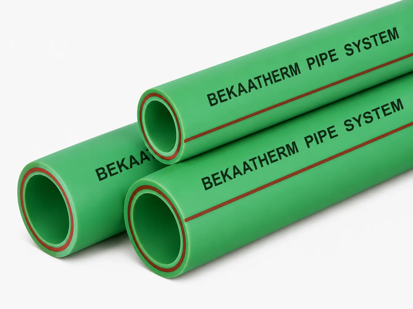
The aluminium layer does two jobs at once, which is what makes it the default for closed-loop heating distribution: it blocks oxygen ingress and holds the pipe against thermal movement. A glass-fibre reinforced middle layer reduces expansion relative to plain PP-R without providing a barrier — good pipe, different purpose. If your circuit is sealed and feeds steel, write the aluminium construction on the schedule. Details on both: aluminium-composite pipe and fibreglass PP-R.
Thermal expansion, worked out
This calculation separates installations that last from installations that start creaking in year two. PP-R expands at 1,5 × 10⁻⁴ K⁻¹ measured to DIN 53712, averaged between 0 °C and 110 °C — 0,15 mm per metre per degree, the way an installer uses it.
Take a 10 m plain PP-R primary, filled cold at 20 °C and brought to 70 °C flow. That is 50 K, so 10 m × 50 K × 0,15 mm = 75 mm. Clamp both ends rigidly and that movement does not disappear — it becomes stress in the pipe wall, load on brackets, and a slow bow in the run. Same arithmetic on aluminium composite at 0,3 × 10⁻⁴ K⁻¹: 10 m × 50 K × 0,03 mm = 15 mm. Same route, one fifth of the movement. That is the engineering reason to put AL-composite on an exposed heating primary, and it is a five-fold reduction, not the vague “about a third” that circulates on supplier blogs.
Either way the design response is the same, and on heating pipework it is not optional: fixed points to decide where the movement goes, sliding supports everywhere else, and expansion loops or offsets sized to absorb the calculated figure. Do the multiplication for your longest straight run before you set out brackets. One more property belongs here — PP-R’s deflection temperature under load is 70 °C at 0,45 N/mm² per ISO 75, which is why bracket spacing on a hot run is tighter than on a cold one. A support interval that looks fine during a cold commissioning walk-round will sag once the system is up to flow.
Loop design, manifolds and EN 1264
EN 1264 is the European series for water-based surface embedded heating and cooling, and knowing which part answers which question saves time: Part 1 definitions, Part 2 floor heating thermal output, Part 3 dimensioning, Part 4 installation, Part 5 wall and ceiling output. The 2021 edition added “and cooling” to the series title — the older series was heating only. Türkiye is bound to implement it, alongside Germany, France, the UK and the rest of CEN.
The 100-metre rule of thumb is a proxy, and 2021 replaced it
Loop lengths of roughly 100 m for 16 mm pipe and 120 m for 18 mm are the figures every installer quotes. They are commonly used rules of thumb, not code requirements — no standards body publishes a fixed maximum loop length, because the real constraint is pressure loss and mass flow.
Here is the detail that is not on a single competitor page: EN 1264-3:2021 added new subclauses to the dimensioning part, including 5.2.1.1 Pressure loss. It became an explicit dimensioning step rather than a rule of thumb. If you still work from a 2009-era calculation sheet, there is a second reason to update — the 2021 revision also corrected Formula (15) from 1/α = 0,009 3 (m²·K)/W to 1/α = 0,092 6 (m²·K)/W. That is a factor of ten in a heat-transfer coefficient, listed quietly among the foreword changes. EN 1264-3 also lists EN 12831 as a normative reference, which fixes the order of work: heat load first, then emitter, then distribution.
Floor surface temperature, stated accurately
EN 1264-3 takes physiological limits into account, and for floor heating those limits are realised through the characteristic curves and limit curves determined per EN 1264-2 — not through a single printed number. The values commonly cited are 29 °C in the occupied zone and 35 °C in the peripheral zone. Use them as design targets, but in a specification cite the limit curves, because that is how the standard expresses it. For ceiling systems, the 2021 revision modified the maximum average surface temperature in subclause 4.2.1.4, with technical commentary putting the new figure at 33 °C.
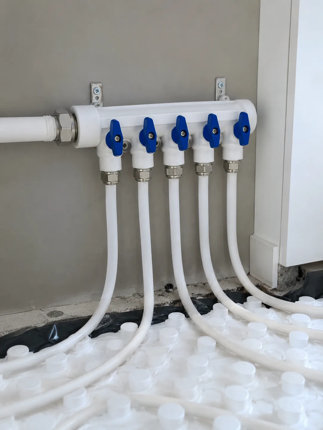
Manifold selection and the transition point
The manifold is where PP-R hands over. Our brass-core manifolds come in 2-way, 3-way, 4-way and 5-way configurations on 32 mm and 40 mm bodies with 1/2 inch female connections. Body size follows total circuit flow, not outlet count. Split into two manifolds rather than pushing one body past its flow capacity — two balanced groups outperform one starved one, and each gets its own commissioning record.
Before the screed goes down, pressure test — and hold pressure while the screed is poured and cures. The point is not the certificate. It is that a barrow wheel through a loop shows up as a falling gauge while the floor is still open, instead of as a damp patch a month after handover. EN 1264-4 is the installation part of the series; take specific test pressures from that document or your local code, not from a blog. Our heat fusion welding guide covers joint preparation on the distribution side, where most avoidable defects start.
End to end: a six-circuit apartment
Take a gas-boiler apartment with six floor circuits, a mixing group holding 45 °C flow, and a plant cupboard eight metres from the manifold. Working the decisions in order:
- Heat load first. EN 12831 gives the room-by-room load. Dimension the floor circuits per EN 1264-3 from that, including the pressure-loss step in 5.2.1.1. Circuit lengths fall out of the calculation, and the 100 m figure becomes a sanity check rather than an input.
- Class. A boiler behind a mixing group whose bypass is not mechanically capped is Class 4, not Class 3 — declare Class 4 and stop worrying about whether someone raises a setpoint later.
- Distribution material. Six circuits on a closed loop feeding a steel boiler means the barrier requirement applies. Aluminium-composite PP-R for the primary legs.
- PN class. PN25. At 70 °C for 50 years that is 10,7 bar against PN20’s 8,5 bar, and 45 °C flow today does not guarantee 45 °C flow after the next boiler replacement.
- Expansion. Eight metres, 20 °C to 45 °C, is 25 K. In AL-composite: 8 × 25 × 0,03 = 6 mm. Small, but it is 30 mm if someone value-engineers to plain PP-R and 30 mm will find the weakest bracket.
- Manifold. Six circuits exceeds a single 5-way body, so either a larger multi-port assembly or two groups. Flow capacity decides the body size, not the outlet count alone.
- Transition. PP-R terminates at the manifold. Flexible barrier loop pipe leaves it, jointless, into the screed. Pressure test, then pour, and hold pressure through the cure.
Nothing in that sequence is exotic. What makes it work is that every choice traces to a number in a standard rather than to a habit, and that the PP-R stops at the manifold instead of one metre past it.
What to ask a supplier at order time
Certification marks are scoped documents, not badges. A mark earned for a cold-water line does not automatically cover heating pipe from the same plant, and the gap only surfaces when a specifier or a customs officer asks. Request the certificate scope, not the logo.
Our reference standards are ISO 15874-1 for general requirements, ISO 15874-2 for pipes, ISO 15874-3 for fittings and ISO 15874-5 for fitness for purpose of the system, alongside DIN 8077 for dimensions and DIN 8078 for quality requirements. Certifications are SKZ (Germany), ISO 15874, CE and WRAS. Production runs across a 120,000 m² plant with 1000+ staff and 10,000 moulds, shipping 98 items across 4 systems to 118+ countries. Details on the PP-R pipe range.
Commercially: a mixed trial order is one 20GP container of pipe, fittings and valves, lead time 15–25 days on regular in-production sizes. Payment is 30% T/T deposit with 70% against copy B/L, and an irrevocable L/C at sight is accepted from USD 50,000. Trade terms are FOB İstanbul or Mersin by default, CFR and CIF on request. Standard samples are free up to 3 items on freight collect if you want to fusion-test a joint first.
A compliance note, offered as guidance rather than a determination. Requirements for oxygen barrier evidence, potable-water approval and system certification differ between jurisdictions. Confirm what your destination market requires before finalising a specification, and ask us for the certificate scope in writing so your consultant can check it against local rules.
Ready to price a heating package?
For importers and project contractors who already know their class, PN and construction. Send the schedule and we will quote FOB with a container loading plan and the certificate package for your market. If you are still comparing constructions, the fibreglass versus aluminium composite comparison is the better next read.
Conclusion
Two decisions carry most of the risk in a PP-R heating specification. The first is the boundary: distribution yes, embedded loops no, solar primary never. The second is reading the pressure rating on both axes, because 32,4 bar at 20 °C and 6,5 bar at 95 °C are the same pipe, and only one of those numbers belongs in your calculation.
If you are specifying now, take your longest straight run and do the expansion arithmetic before anything else — it will tell you quickly whether plain PP-R or aluminium composite is the honest answer for that route. Then check that whatever your supplier sends you names an ISO 10508 class.
Frequently Asked Questions
Can PPR pipe be used for underfloor heating?
Yes for the distribution side — risers, primaries, manifold tails and radiator drops — but not for the embedded loops in the screed. PP-R is joined by socket fusion and would put buried joints in a floor, and its thermal conductivity of 0,23 W/m·K makes it a poor thin-wall emitter. Use flexible barrier loop pipe past the manifold.
What temperature can PPR pipe actually handle continuously?
Published DIN 8078 operating-condition data lists PN25 PP-R at 10,7 bar for 50 years at 70 °C, but only 8,1 bar for 25 years at 80 °C and 6,5 bar for 5 years at 95 °C. The service life shortens as temperature rises. Treat 70 °C as the sustainable design ceiling for a 50-year heating circuit.
Is PN20 or PN25 better for a heating circuit?
PN25 for heating duty. At 70 °C over a 50-year design life, published DIN 8078 data gives PN25 10,7 bar against PN20’s 8,5 bar — about 26% more allowable working pressure for a wall-thickness change. PN20 remains sensible on cold and warm domestic water legs.
Can PPR pipe be used on a solar hot water system?
Only on the secondary side, downstream of the heat exchanger or storage cylinder and downstream of a tempering valve. Never on the collector primary loop. ISO 9806:2017 measures collector stagnation temperature specifically so that piping material can be chosen correctly, and stagnation exceeds any thermoplastic’s service range.
Does underfloor heating pipe need an oxygen barrier?
Yes on any sealed circuit containing steel or cast iron components. DIN 4726, as applied by DIN CERTCO, limits oxygen permeability to 0,32 mg/(m²·d) at 40 °C for application class 4 and 3,60 mg/(m²·d) at 80 °C for class 5. Aluminium-composite PP-R provides that barrier on the distribution side.
How much does PPR pipe expand when it heats up?
Plain PP-R expands 0,15 mm per metre per degree, so a 10 m run taken from 20 °C to 70 °C moves 75 mm. Aluminium-composite PP-R moves 0,03 mm per metre per degree, giving 15 mm over the same run. Size expansion loops and sliding supports from whichever figure applies to your pipe.
How long can an underfloor heating loop be?
Roughly 100 m for 16 mm pipe and 120 m for 18 mm are common rules of thumb, not code requirements. The real limit is pressure loss and mass flow, and EN 1264-3:2021 added an explicit Pressure loss subclause at 5.2.1.1 that makes this a calculation rather than a guess.