Most HDPE pipe installation failures are not jointing failures. The trench is open, the string is joined and the welds are sound, and the line still comes back six months later as a flat spot under a service road or a coupling that has pulled itself apart. The work that decided that outcome happened around the joint, not at it — in the material that went back into the trench, in how long the pipe was left to settle before the tie-in, and in how the acceptance test was run.
This page covers the laying and acceptance half of the job: trench geometry, embedment grading, thermal allowance and the pressure test clock. It is deliberately not about how joints are made — if you are still choosing between fusion and mechanical connection, that decision belongs on our comparison of HDPE pipe jointing methods. Here the joint is simply an event in a sequence, and everything around it is what gets inspected.
Key takeaways
- PE is a flexible pipe. It carries load through the compacted soil around it, not through its own wall — so the embedment material is the structure, and unscreened spoil cancels the design.
- A “≥95% compaction” line on a drawing is incomplete without its test method. For crushed rock the standard Proctor test is the wrong reference, and a nuclear gauge is not a valid measurement at all.
- Buried PE does not expand and contract freely. Soil friction converts thermal movement into wall stress, which is why snaking is specified only up to DN110 and why the real risk at a tie-in is contraction pull-out.
- The pressure test is not “1.5 times design pressure for two hours”. PE creeps under test pressure, so the recognised procedures use a multi-phase clock with a relaxation period and a rising-pressure pass criterion.
- Fix the pipe standard, the SDR and the fitting pressure class at order time. A crew waiting in an open trench for the right fitting is a scheduling problem created weeks earlier on the purchase order.
The three places a buried HDPE line gets sent back
Start with the fact that governs everything else, because almost every argument on site traces back to people not agreeing on it. The Plastics Pipe Institute’s handbook chapter on underground installation, revised and published in November 2025, states it plainly: “PE pipe is designed and installed as a flexible pipe… the pipe deflects due to load, which develops lateral soil support to resist the deflection. An optimal design is a combination of the pipe stiffness and the soil stiffness that will support the loads on the pipe.”
Read that as an instruction rather than a description. A concrete or ductile iron pipe is a structure that happens to be buried. A PE pipe is half a structure; the other half is the soil you pack around it, and you build that half on site with whatever the excavator has in the spoil heap.
The pipe arrives from the factory with its performance fixed by SDR and material grade. The soil half is built by the crew, in the dark, under time pressure, and it is the half nobody photographs.
That is why the same three arguments recur on buried PE projects across every market we ship into, and why this article is organised around them rather than around a generic step list:
- The backfill — whether the material going back around the pipe is graded embedment or the same clay that came out, and what the compaction figure on the drawing actually requires.
- The thermal allowance — what to do with a pipe string that has been lying in the sun before it is connected and covered.
- The test — how long the acceptance test runs, at what pressure, and what counts as a pass when the gauge will not sit still.
Each gets its own section below, with the numbers and their sources. Two notes on how to read them. First, the most complete published installation figures are American — ASTM D2321, ASTM D2774 and AWWA M55, quoted here in their original imperial units with metric alongside.
If your tender is written against ISO 4427, EN 12201, EN 805 or EN 1610, as most tenders in the Gulf, North and West Africa and Central Asia are, the engineering is the same and the clause numbers are not; check your project specification for the figure and use the American documents to understand why the figure exists. Second, where a project specification and a general practice document disagree, the project specification wins. Nothing below overrides a signed contract document.
Trench geometry: width, bedding, and the ground under the bedding
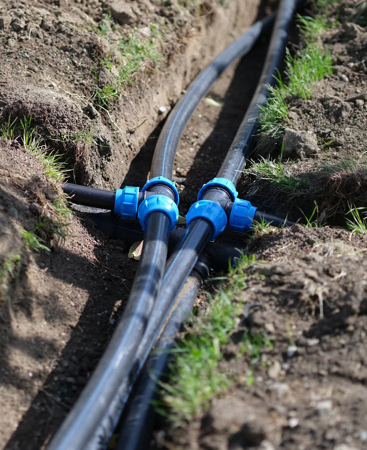
Trench width is not a safety-and-access number alone — it sets how much room a compactor has beside the pipe, which sets how much lateral support the pipe gets. For a Basic Installation the PPI handbook gives a minimum trench width of 12 in (305 mm) for pipe under 3 in (76 mm) nominal OD, and pipe OD plus 12 in for pipe from 3 to 24 in (76 to 610 mm).
Where two pipes share a trench, the clearance between them is 4 in (102 mm) for the small sizes and 6 in (152 mm) for the larger range.
Trench boxes and shoring make the excavation wider than these minimums; the numbers are what must remain around the pipe, not what the digger cuts.
Bedding thickness and cover depth
Bedding thickness runs 4 in (102 mm) for pipe under 60 in (1,524 mm) diameter and 6 in (152 mm) for 60 in and above.
There is one adjustment that gets missed constantly: “If the bottom of the trench is rock or contains cobbles or boulders, the bedding thickness should be increased by at least two inches” — an extra 2 in (51 mm) on rock. Excavate recesses for couplings, flanges and adaptors as well, so the barrel of the pipe sits on the bedding along its length rather than bridging between two connectors.
Cover depth in the PPI field manual runs between 2.5 ft (0.76 m) and 25 ft (7.6 m), with a 3.0 ft (0.91 m) minimum wherever vehicle traffic passes over the line. Below the bedding, the native foundation and the trench walls have to be stable and give the pipe continuous support; soft spots get replaced or reinforced before any bedding goes in, and expansive clays, collapsing soils or landfill push the job out of the simple case entirely.
That last point is the real decision in this section. There are two installation regimes, and knowing which one you are in determines whether the rest is a lookup or a calculation.
| Condition | Basic Installation applies when | Otherwise |
|---|---|---|
| Pipe diameter | 24 in (610 mm) or less | Engineered Installation: embedment soil and percent compaction are selected by calculation, with deflection checked against the actual backfill, surcharge and live loads. Class III and IV soils are evaluated by a geotechnical engineer; Class V is not used at all. |
| Wall thickness ratio | DR 21 or less | |
| Depth of cover | 10 ft (3.05 m) or less | |
| Groundwater | Natural water table below the pipe | |
| Loading | No live load and no surcharge load | |
| Foundation | Not expansive clay, collapsing soil or landfill | |
| Particle size | Within the embedment limits in the next section |
All seven conditions have to hold together. A DR 17 line at 200 mm under a field is a Basic Installation; run the same line under the access road at the end of that field and the live load alone moves it into Engineered territory, where somebody has to select the embedment and the compaction and check the resulting deflection. The transition happens along a single alignment, which is exactly the situation where crews carry the field detail past the point where it applies.
One construction detail belongs here because it destroys good work invisibly. Where a trench box is used, embedment has to be compacted against the trench wall, not against the box. The handbook is explicit about the consequence: “If compacted against the trench box and the trench box is moved, a void is left that can cause excessive deflection.” The compaction test passes, the box advances, and the support the test measured is dragged forward with it.
Rework point 1: the backfill grading that decides whether the pipe survives
This is the question every foreman asks and most specifications answer badly: can the spoil go back in? The material around the pipe is graded into five classes in descending order of stiffness once compacted, and the class decides both whether it is usable and how it must be compacted.
| Class | What it is | Use in the pipe zone | Compacts best by |
|---|---|---|---|
| Class I | Crushed rock: 100% passing 1½ in sieve, ≤25% passing 3/8 in, ≤15% passing a No. 4 sieve, ≤12% fines, all faces fractured | Preferred — highest stiffness | Vibration |
| Class II | Clean coarse-grained soils (GW, GP, SW, SP), up to 12% fines | Preferred | Vibration |
| Class III | Coarse-grained soils with fines; sandy or gravelly fine-grained soils with ≥30% retained on a No. 200 sieve | Only on geotechnical evaluation | Impact or kneading |
| Class IV | Fine-grained soils with <30% retained on a No. 200 sieve (ML, CL) | Only on geotechnical evaluation | Impact or kneading |
| Class V | High-compressibility silts and clays, organic soils (MH, CH, OL, OH, Pt) | Not used — excluded outright | — |
So the answer to “can we use the spoil” is: only if the spoil is Class I, II, or a Class III or IV that an engineer has signed off, and only if it meets the particle size limit for the pipe diameter.
Those limits are tight — ½ in (13 mm) maximum particle for pipe up to 4 in (102 mm), ¾ in (19 mm) for 6 to 8 in (152 to 203 mm), 1 in (25 mm) for 10 to 16 in (254 to 406 mm), and 1½ in (38 mm) for 18 in (457 mm) and larger.
There is also a trap for sandy sites: uniform fine sands with more than 50% passing a No. 100 sieve must be treated as Class III material regardless of what the symbol on the sheet says, which quietly moves a “clean sand” site into engineer-sign-off territory.
The compaction line on your drawing is probably incomplete
This is the detail worth the price of the page, because it is missing from every general installation guide currently ranking for this subject, and it produces test certificates that do not mean what the reader assumes.
Percent compaction is a ratio of field density to laboratory maximum density. The laboratory maximum density is not one number — it depends on which test produced it. The handbook’s convention is unambiguous: “The percent of the maximum density of the soil is followed by the ASTM test procedure used to determine the maximum density. For example, ≥95% (D698) means that the in-place density should be equal to or higher than 95 percent of the maximum density obtained using D698.”
And the correct laboratory test depends on the soil class. For Class III or IV soils, the standard Proctor compaction test (ASTM D698) is the reference. For Class I or II soils — the crushed rock and clean coarse material you actually want in the pipe zone — the preferred test is a vibratory compaction test: ASTM D4253 using a vibratory table, or ASTM D7382 using a vibratory hammer, and the handbook notes that “D7382 is considered more reliable than D4253.”
Put those together and a specification reading “compact embedment to 95% Standard Proctor” on a crushed-rock pipe zone is citing a laboratory reference that does not properly apply to the material specified.
The measurement side has the same problem: the nuclear gauge, which is what most site labs reach for, “is not appropriate for Class I soils and Class II gravel soils.” A crew can pass a compaction test on crushed rock with an instrument that is not valid for it, and hand over a certificate that satisfies the file and not the pipe.
If you are writing or reviewing a specification, name the test with the percentage. If you are receiving one, ask which laboratory reference and which field instrument the figure was produced against before you accept it as proof of support.
The haunch zone, and where structural support stops
Placement technique matters more here than compactive effort. The zone under the springline, in the haunches, is the part that carries the pipe and the part that is hardest to reach. The handbook is direct: “A successful installation depends on the correct placement and compaction of soil in the haunch zone of the pipe. The first few lifts should be placed so that the embedment materials can be shovel sliced into the haunches.”
Where shovel slicing is impractical, the preferred alternatives are flowable fill, or compacting Class I or Class II soils with saturation and vibration per ASTM F1668. If flowable fill is used in the haunch zone, it should be used as the bedding too.
Above the haunches, three rules govern the rest of the pipe zone. Lifts go in at no more than 6 in (152 mm) thickness, mechanically tamped to at least 85% Standard Proctor Density, rising to 95% under streets and roads.
The initial backfill “should not be compacted directly over the top of the pipe” — the crown takes the load through the sides, not from a plate compactor above it. And the structural work of the initial backfill is finished higher than most crews assume: it “provides structural support for the pipe up to about 75% of the outside diameter of the pipe”, above which it is cover rather than structure.
Water, and finding the pipe again
Two site conditions modify this. Where the embedment sits below the water table, Class I or Class II material may be wrapped in a geotextile to stop fines migrating in from the trench walls and backfill — without it, the graded stone you paid for slowly fills with the clay you excluded, and the support you designed leaks away over a few seasons.
And once the line is covered, PE is invisible to a metal detector, so tracer wire goes in with it, approved by the engineer and placed no more than 6 in (152 mm) above the top of the pipe.
The reason all of this is enforced with such specificity is deflection. AWWA M55 recommends an allowable long-term ring deflection of 7.5% — a figure widely reported from that manual, though the manual itself is a paid standard and the number here is quoted from secondary technical reporting rather than read from the source document. Treat it as the order of magnitude the industry designs against rather than as your project’s acceptance limit, which will be stated in your own specification.
What is not in doubt is the mechanism: the two failure paths named in the handbook, a trench-box void and an unsupported haunch, both work by removing lateral support, and both are invisible from the surface until the line is measured.
Rework point 2: thermal movement, and why leaving a snake in the trench is only half right
The standard advice — lay the pipe in a serpentine so it has slack to expand and contract — is repeated on nearly every installation page for this subject. It is correct in a narrow set of cases and misleading in most, and the difference is worth understanding because the failure it causes shows up at joints rather than in the pipe barrel.
PE moves a lot with temperature. Vinidex, publishing technical data for its PE pressure pipe, gives “an average value of 2.0 x 10⁻⁴ /°C” for linear thermal expansion — 0.2 mm per metre for every degree. On a 100 m string that is 20 mm per degree, and a black pipe lying in Gulf or Sahel sun can easily sit 25 to 30°C above the trench temperature it will settle to. That arithmetic is what drives the snaking advice.
Except that once the pipe is buried, it is not free to move. The same source states what actually happens: “the frictional support of the backfill against the outside of the pipe restrains the movement and any thermal effects are translated into stress in the wall of the pipe.”
A backfilled line does not shorten by 20 mm per degree. It develops longitudinal stress instead, and a snake that has been compacted into graded stone is not a movement allowance any more — it is a permanent bend with soil packed around it.
So the guidance narrows to something you can act on. Vinidex specifies snaking “for small sizes (up to DN110) and allowing the temperature to stabilise prior to backfilling”; above that diameter, “the final connection should be left until the pipe temperature has stabilised.” The controlling action for a large-diameter line is not the snake. It is the wait.
What actually breaks: contraction at the tie-in
The real hazard runs the other way from the one people plan for. The PPI handbook: “Placing pipe that has been in direct sunlight in a cooler trench will result in thermal contraction of the pipe. This contraction can generate force which could result in pull-out at mechanical couplings or other buried structures. Allow pipe to cool before making connections to an anchored joint, flange, or a fitting that requires protection against excessive pull-out forces. Methods to facilitate cooling include covering the pipe with soil.”
A hot string connected into a cold chamber does not push. It pulls, and it pulls hardest at the mechanical connection or the anchored structure at the end of the run — the compression coupling, the flanged transition into a valve chamber, the connection to a rigid pipe of another material. Covering the pipe with soil to bring its temperature down is a legitimate technique and it costs an hour of programme, which is why it gets skipped.
Where anchor blocks are designed for a PE line, two forces combine. The handbook sets the pull-out design force as the sum of the Poisson force and the thermal force, using a long-term Poisson’s ratio of 0.45 for working pressure and a short-term 0.35 for occasional surge. Anyone sizing a thrust or anchor block from thermal movement alone is designing against half the load.
Bending radius and hot-climate derating
PE will take a cold field bend, within limits that tighten as the wall gets thinner and tighten dramatically near a fitting.
| Pipe DR | Minimum long-term cold bending radius | On a 200 mm OD pipe |
|---|---|---|
| DR 9 | 20 × pipe OD | 4.0 m |
| DR 11 and 13.5 | 25 × pipe OD | 5.0 m |
| DR 17 and 21 | 27 × pipe OD | 5.4 m |
| Any DR, fitting or flange in the bend | 100 × pipe OD | 20.0 m |
The last row is the one that catches people. A fitting present in or planned for a bend takes the minimum radius to 100 times OD, observed for about five pipe diameters either side of the fitting.
On a 200 mm line that is a 20 m radius through the fitting zone against 5.4 m for the plain pipe — a completely different alignment, decided by whether a saddle or coupling ends up in the curve. The published radii already include a safety factor against kinking of at least 2, so they are not conservative numbers waiting to be shaved.
One more temperature effect belongs on the order sheet rather than in the trench. Pressure ratings are stated at 20°C, and warm water or warm ground derates them. Vinidex publishes design factors for PE100 of 1.0 to 1.1 at 20 to 30°C, 1.2 at 35 to 40°C, 1.3 at 45°C and 1.4 at 50 to 55°C. A line that will run at 40°C in service needs its pressure class chosen against that factor at specification time — it is not something the installation can compensate for.
Rework point 3: how long the pressure test is actually held
Ask for a hold time and someone will say 1.5 times design pressure for two hours. That is rigid-pipe practice, and applying it to PE produces failed tests on sound pipelines and passed tests on leaking ones. The reason is in the first line of the Plastics Industry Pipe Association’s technical note on hydrostatic field pressure testing of PE pipes: PE pipes “are subject to creep under constant loading and will expand due to the action of internal test pressure.”
A pressurised PE line grows. The gauge falls because the pipe is still expanding, not because water is escaping, and there is no way to tell those two apart by watching a needle drop. The recognised procedures — EN 805 in Europe, IGN 4-01-03 in the UK, ASTM F2164 and PPI TN-46 in the United States, VAV P78 in Sweden — all solve it by structuring the test in phases so that expansion is separated from leakage.
Start with the pressure. System Test Pressure is “at least 1.25 times maximum working pressure of pipeline or 1.25 times the PN rating of the pipe, but is not to exceed 1.25 times the maximum allowable operation pressure (MAOP) of the lowest pressure rated pipe or fitting in the line.” Two things follow. The multiplier is 1.25, not 1.5. And the ceiling is set by the weakest rated component in the line, not by the pipe — a PN16 main with PN10 compression fittings on it is tested against the fittings.
Before any pressure goes on
Air is the thing that ruins PE pressure tests, because compressed air stores energy that mimics pipe expansion. The technical note is blunt: “the removal of both entrapped and dissolved air is critical to successful pressure testing. The presence of air can distort the test results and mask the presence of a leak.” Fill from the lowest point in the pipeline and restrict the entry velocity to 0.05 m/s so air is not driven ahead into downward-sloping sections, then flush, swab and vent.
Note also that exposed pipe warming during the test window changes pipe volume, distorting the reading, so a test run across the middle of a hot day on an uncovered string is being asked to measure two things at once.
One safety rule overrides convenience: pneumatic testing “should be avoided due to OH&S concerns arising from the substantial energy stored in a compressed gas.” Test water lines with water.
The rebound method clock
This is the procedure most projects will run on a jointed buried line where the joints are not visible for inspection.
| Phase | Action | Time | Reading |
|---|---|---|---|
| Preliminary | Reduce to atmospheric, let stand | 60 min | — |
| Preliminary | Raise to STP in under 10 min, hold and pump as needed | 30 min | Inspect for leaks |
| Preliminary | Shut off pressure, let stand | 60 min | P60 must exceed 70% of STP |
| Main | Bleed pressure down by 10–15% of STP, measure water bled | under 5 min | Compare against calculated maximum |
| Main | Observe and record the pressure rise | 30 min | Pressure must rise or stay static |
| Main, if in doubt | Extend the observation | 90 min | Maximum allowable drop 20 kPa |
The pass criteria are that there are no leaks, no components break, and the internal pressure rises or remains static over the 30-minute observation.
That rising gauge is the point of the whole exercise. Having been bled down, a sound viscoelastic pipe recovers and pushes the pressure back up; a leaking one cannot. It inverts the intuition a crew brings from steel and ductile iron, where a rising gauge means somebody left a pump running, and it is worth telling the site team before the test rather than during it.
Two shortcuts exist and both have conditions attached. Where the pipe and fitting joints are accessible for inspection, “there is no evidence of leaks of the test water after at least 15 minutes” is enough to deem the section passed — that is the small, short, visible-joint case, not the buried main.
Where joints are not accessible, a simplified route allows a minimum 2 h test with apparent water loss below Q < 0.14 L·D·H litres per hour, where D is internal diameter in metres, L is test length in kilometres and H is average test head in metres.
When a result is marginal, or when a leak has to be quantified rather than merely detected, the reference method applies: pressurise to STP and let the line settle for at least 12 hours, then raise to STP again and hold for 5 hours, recording make-up water between the 2nd and 3rd hours and between the 4th and 5th. The line passes if ΔV(5h−4h) ≤ 0.55 ΔV(3h−2h) + Vleak1h. Budget the better part of a day for it, and note that this is the procedure to nominate in a contract where a disputed test would otherwise stop payment.
The sequence, in the order the work actually happens
Here is the same material as a run order, with the condition that stops the job at each step. It assumes a jointed buried pressure line in the Basic Installation envelope; anything outside that envelope has an engineer’s embedment and compaction schedule attached, and that schedule replaces the general figures below.
- Accept the trench floor. Foundation and walls stable and giving continuous support. Soft, expansive or collapsing ground is corrected before bedding, not compensated for afterwards. Stop condition: soft spots present.
- Place bedding. 4 in (102 mm) under pipe below 60 in diameter, 6 in (152 mm) at 60 in and above, plus 2 in (51 mm) where the floor is rock or cobbles. Excavate recesses for every coupling and flange. Stop condition: the pipe barrel bridges between connectors instead of resting on bedding.
- Lay and connect, watching temperature. Make joints per the jointing procedure, but hold the final tie-in into any anchored structure or mechanical coupling until the pipe temperature has settled — cover with soil to speed it up. Snake only up to DN110, and only if the temperature stabilises before backfill. Stop condition: a hot string about to be closed into a cold chamber.
- Haunch. Shovel-slice the first lifts into the haunches, or use flowable fill, or saturate and vibrate Class I/II material. This step carries the pipe. Stop condition: material bridging over the haunch leaving a void under the springline.
- Initial backfill to the structural line. Lifts no thicker than 6 in (152 mm), tamped to at least 85% Standard Proctor, 95% under roads, with the correct laboratory reference named for the soil class in use. Nothing compacted directly over the crown. Support work is done at about 75% of OD. Geotextile wrap if the embedment is below the water table. Stop condition: a trench box moved before its adjacent embedment was compacted against the trench wall.
- Tracer wire and final backfill. Wire no more than 6 in (152 mm) above the pipe crown, engineer-approved, because nothing will find this pipe later without it. Final backfill free of large lumps, organics and oversized stone. Stop condition: no locating provision installed.
- Fill, vent and test. Fill from the low point at 0.05 m/s, flush and vent all air, then run the phase clock above at 1.25 × the rating of the weakest component. Stop condition: a falling gauge during the observation window.
- Record. Keep the test sheet with its phase times, the compaction results with their laboratory reference and field instrument named, and the pipe’s own delivery documentation. The compaction certificate is the one most likely to be challenged later, and it is the one whose validity depends on details in step 5.
Steps 3, 5 and 7 are the three rework points. If a programme is under pressure and something has to give, those are the three places where saving an hour costs a section.
Ordering the pipe so the trench crew is not improvising
Most of what stops a trench crew was decided weeks earlier by whoever wrote the purchase order. The pressure class was chosen without the service temperature; the fitting range stopped at a size the drawing needed; the pipe arrived to a standard the consultant did not recognise. None of that is fixable in the trench, so it is worth being specific about what to fix at order time.
Name the standards on the order. Bekaatherm manufactures HDPE and PE pipe to ISO 4427 and EN 12201, with dimensions to DIN 8074 and 8075, and PP compression fittings to ISO 14236. Those designations are what a consulting engineer checks a submittal against, and getting them onto the order is what makes the submittal straightforward rather than a round of correspondence. If you are still fixing the wall thickness, our breakdown of SDR, PN and wall thickness covers how the pressure class and the dimension ratio relate.
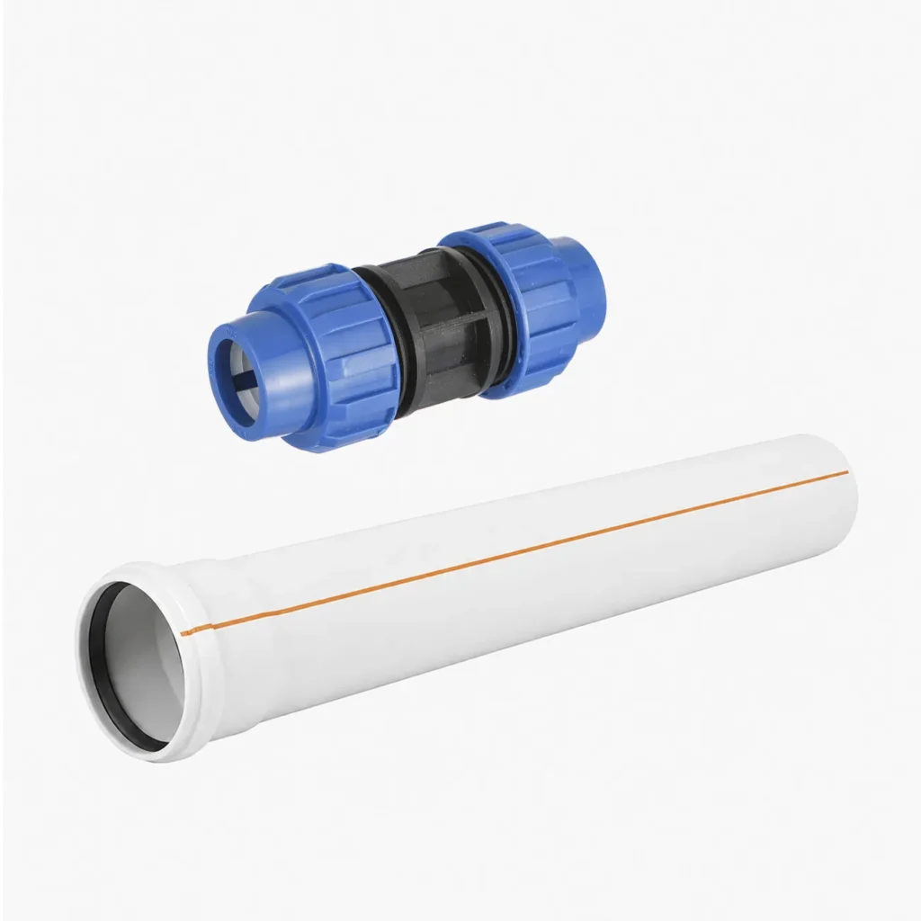
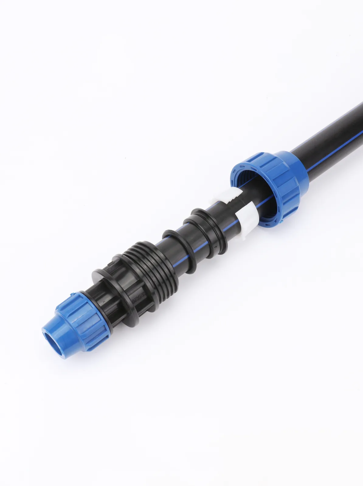
Fix the connection range at the same time. The weld-free route on a buried line is mechanical compression, and it has a size and pressure ceiling that has to match the drawing before the order is placed rather than after.
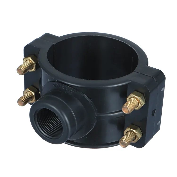
Our HDPE compression fittings range runs from 20 to 110 mm with saddle clamps up to 315 mm, all rated PN10 — which is exactly the constraint that sets the test pressure ceiling discussed above, since the line is tested against its lowest-rated component. Above that range or above that pressure class, the design moves to fusion and the equipment question comes with it.
The commercial terms that decide the programme
| Item | Position |
|---|---|
| Minimum order, trial | One 20GP mixed container (pipe + fittings + valves) |
| Minimum order, single specification | 500 kg per size and colour |
| Minimum order, private label | One 40HQ, or 3 tonnes per colour on a first branded run |
| Lead time, regular sizes | 15–25 days |
| Lead time, private label | 30–45 days, add 7–10 days for a first colour match or new mould |
| Pre-order verification | Standard items: up to 3 supplied free of charge, freight collect. Branded items: 7–10 days, cost credited against the first bulk order. Terms are agreed per enquiry. |
| Payment | 30% T/T deposit, 70% against copy B/L; irrevocable L/C at sight accepted from USD 50,000 |
| Trade terms and volume | FOB İstanbul or Mersin by default, CFR and CIF on request; a 20GP gives roughly 33 m³ usable against a ~28 tonne payload, a 40HQ roughly 76 m³ |
| Warranty | 50-year warranty against material and manufacturing defects |
Two of those lines interact with the programme directly. A 15–25 day lead time on regular sizes means a size discovered missing when the trench is already open is a month, not a week — which is the argument for ordering the saddle and transition range against the drawing rather than against the pipe schedule alone.
And the 500 kg per size and colour minimum is why a project with a long tail of odd sizes is usually better served by consolidating the tail into a mixed container than by ordering each size to its exact requirement.
On verification before committing to a container: physical items for checking dimensions and markings are covered by the terms in the table above, with standard items limited to three and branded items running 7–10 days.
There is no self-service form for this — the quantity, the destination and the freight arrangement are agreed by email or WhatsApp against your specific size list, since a saddle-and-transition check for a buried network is a different request from a colour match for a branded run. Third-party inspection at the factory before shipment is arranged the same way. How batch testing and production control work in this factory is set out on our quality control and testing page, which documents the regime on the PPR line in most detail.
Where we stop
Where we stop is worth stating plainly, because it changes what this page can do for you. Bekaatherm manufactures the pipe and the PP compression fittings — 20 to 110 mm, saddle clamps to 315 mm, all PN10, to ISO 4427, EN 12201 and ISO 14236. Butt-fusion and electrofusion fittings are not in the range, welding equipment is not supplied, and nothing written here replaces your project specification or your engineer’s embedment design. On a line above PN10 or above 110 mm at the joint, the fitting decision moves to fusion and this supplier is the pipe half of that project, not the whole of it.
On price, our position is that a number without its basis is not usable: a quotation states the FOB unit price, the container loading plan and the conformity documentation together, because the same unit price against a different loading plan is a different landed cost. Pricing is quoted per enquiry rather than published, since it moves with resin and with the size mix. What drives it is set out in our note on what actually moves an HDPE pipe price.
Sending a size list for a buried network?
For contractors and importers who have their drawing and want the pipe standard, the compression range and the pressure class checked against it before ordering: send the size list with the service temperature and the tender’s referenced standard, and you will get the matching specification, the MOQ structure for your mix, and lead times on the sizes you actually need. Quotations state the FOB unit price and the container loading plan together, since the same unit price against a different loading plan is a different landed cost. Response within 24 hours.
Frequently asked questions
Can I backfill HDPE pipe with the soil I dug out of the trench?
Only if it qualifies. Class I and II soils are preferred, Class III and IV need geotechnical evaluation, and Class V is excluded entirely. The spoil must also meet the particle size limit for your pipe diameter.
What is the maximum stone size allowed against an HDPE pipe?
It scales with pipe diameter: ½ in (13 mm) up to 4 in pipe, ¾ in (19 mm) for 6 to 8 in, 1 in (25 mm) for 10 to 16 in, 1½ in (38 mm) above. Oversized particles concentrate point loads.
How wide should the trench be for HDPE pipe?
For a Basic Installation, 12 in (305 mm) minimum under 3 in nominal OD, and pipe OD plus 12 in from 3 to 24 in. The width must leave room to compact embedment beside the pipe, which is what supports it.
Do I need to leave a snake in the trench for thermal expansion?
Only up to DN110, and only if the temperature stabilises before backfill. Above that, leave the final connection until the pipe temperature settles — buried pipe is restrained by soil friction and cannot move freely anyway.
What test pressure and hold time does HDPE pipe need?
System Test Pressure is 1.25 times the working pressure or PN rating, capped by the lowest-rated component. The rebound method then runs a phased clock: 60 minutes relaxed, 30 at pressure, 60 standing, then a 30-minute observation.
Why does the pressure rise during an HDPE pressure test?
Because PE is viscoelastic. After the test pressure is bled down by 10 to 15 percent, a sound pipe recovers and pushes the pressure back up. A rising or static gauge over 30 minutes is the pass criterion, not a fault.
How much deflection is acceptable in a buried HDPE pipe?
AWWA M55 is widely reported as recommending 7.5% allowable long-term ring deflection, but your acceptance limit is whatever your project specification states. Deflection is controlled by haunch compaction and by avoiding voids, not by pipe stiffness alone.
What does “compact to 95%” actually require?
It requires a named laboratory test as well as a percentage. Standard Proctor (ASTM D698) is the reference for Class III and IV soils; Class I and II use vibratory methods (ASTM D4253 or D7382), where a nuclear gauge is invalid.
Conclusion
Buried HDPE performs as well as the soil envelope built around it, which means the material grading, the haunch technique and the compaction reference matter as much as the pipe specification. The thermal question is not how much slack to leave but how long to wait before closing the tie-in, and the acceptance test is a phased procedure with a rising-pressure pass criterion rather than a single hold time.
If you are specifying or ordering pipe for a buried network and want the standard, the compression range and the pressure class checked against your drawing before the order goes out, send the size list with the service temperature and the referenced standard. Where your project specification differs from the general practice quoted here, follow the specification.