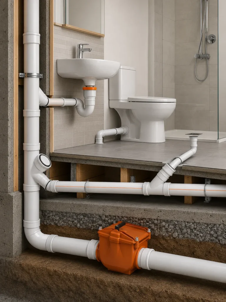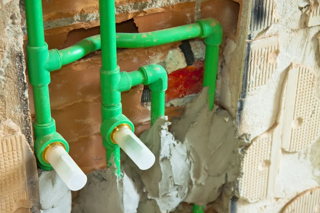
A PN20 pipe is not tested at 30 bar. That single sentence contradicts most of what the first page of Google says about pressure testing PPR, and it is the reason plenty of installers spend an afternoon chasing a “leak” that never existed. Under EN 806-4:2010 (published in Germany as DIN EN 806-4 and in the UK as BS EN 806-4:2010), the site test pressure comes from the maximum design pressure of the installation — the pressure the system will actually see in service — not from the PN class stamped on the pipe. Get that wrong and you either over-stress a system for no reason or sign off a test that proved nothing.
Key Takeaways
- Test pressure = 1.1 × maximum design pressure (MDP), applied by pumping. Not 1.5× the pipe’s PN rating. On a system with 5 bar maximum working pressure, EN 806-4 gives 1.1 × (1.5 × 5) = 8.25 bar.
- Plastic gets its own procedure. EN 806-4 offers two acceptable methods for systems containing plastic — Test A and Test B — because the procedure has to absorb the expansion of the plastic caused by pressurisation. The rigid-pipe method for copper and stainless must not be applied to PPR.
- Test B timing is 30 + 30 + 120 minutes. Allowable drop: no more than 0.6 bar over the first 30 minutes without pumping, then no more than a further 0.2 bar over the following 120 minutes, with no visible leakage.
- Most “failed” tests are thermometer problems. A temperature difference greater than 10 K between pipe and test water requires equalisation before you read anything. Use a gauge that resolves 0.1 bar, fitted at the lowest point of the system.
- Passing the test is not commissioning. EN 806-4 flushing calls for a minimum flow velocity of 2 m/s with the water in the system replaced at least 20 times, and a water-filled system left standing must be exchanged at the latest after seven days.
- The site test and the factory test are different animals. ISO 15874-2 qualifies the material at 16.0 MPa hoop stress for 1 h at 20 °C and 3.5 MPa for 1000 h at 95 °C. Your site test proves the joints; the mill certificate proves the pipe.
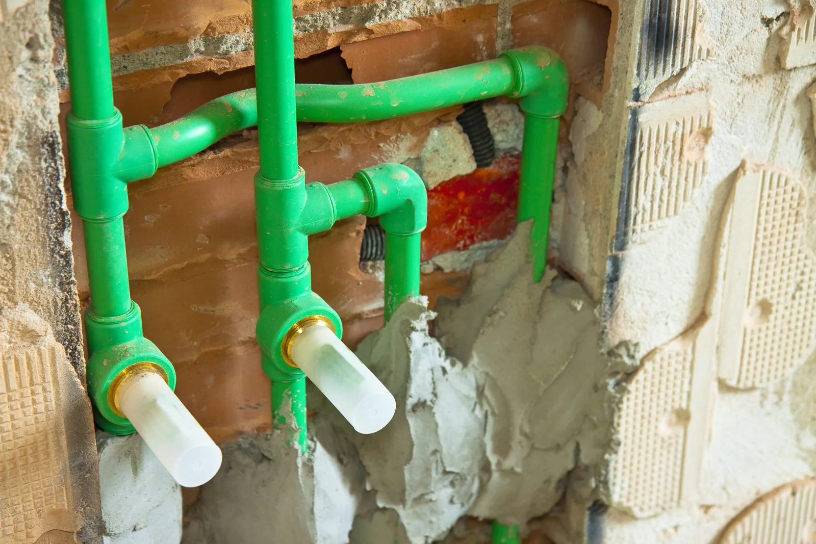
Why the “1.5 × PN rating” rule is wrong
PN20 means the pipe is rated to hold 20 bar of continuous internal pressure at 20 °C for its design life. It is a material qualification, not a test instruction. When a competitor page tells you to test a PN20 system at 30 bar, it has silently swapped the pipe’s rating for the installation’s design pressure — two different numbers that happen to sit near each other in the datasheet.
EN 806-4 anchors the test to maximum design pressure. Test pressure is 1.1 × MDP, reached by pumping. In UK practice that chains together with the statutory requirement: the Water Fittings Regulations and the Scottish Water Byelaws (Schedule 2, Paragraph 5) want at least 1.5 × the maximum working pressure, so on a 5 bar system the statutory floor is 7.5 bar and the EN 806 figure is 1.1 × 7.5 = 8.25 bar. Because EN 806 lands slightly higher, an installation that satisfies EN 806 complies with the Regulations by default. The same relationship is sometimes written as 1.65 × maximum operating pressure.
Now hold that against 30 bar. A domestic riser designed for 5 bar would be tested at 8.25 bar under the standard. Testing it at 30 bar is nearly four times the required pressure — and while a sound PN20 pipe will survive it, every threaded transition, every valve, every appliance connection and every gauge in that circuit is now being asked to do something no one designed it for. You are not proving the installation. You are auditioning the weakest brass insert on the job.
There is a second, quieter cost. If you test at an arbitrary high pressure and something lets go, you have no defensible number to put in the report. A test pressure derived from MDP is traceable to a clause. A test pressure derived from a blog post is not, and it is worthless the moment a warranty claim or an insurance question comes up.
Where specs disagree, and why. If your project spec quotes 1.5 × admissible operating pressure rather than 1.1 × MDP, it is almost certainly written against DIN 1988-2, the older German two-stage form. Both are legitimate; they simply define the multiplier against different baselines. Check which document your contract actually names before you argue with the site engineer.
Why plastic pipe needs a different procedure than copper
EN 806-4 splits the test procedures by material for a physical reason. Systems containing plastic need a method that makes allowance for the expansion in the plastic material caused by the pressurisation process. Polypropylene is visco-elastic — put it under pressure and it does not simply stop deforming the way copper does. It keeps creeping outward for a while, the internal volume grows fractionally, and the gauge falls. Nothing has leaked. The pipe has stretched.
This is why the plastic procedures include a sustained pumping phase up front: you keep topping the system up for 30 minutes so that the bulk of the elastic expansion happens while you are still feeding it, not afterwards during the reading window. A rigid-pipe procedure has no such phase, because copper does not need one. Apply the copper method to a PPR riser and you will record a falling gauge and call it a failure.
There are two acceptable procedures for plastic systems, and the choice is genuinely yours. Test A is the shorter, more forgiving one. Test B is the one specifiers ask for when the handover documentation has to stand up to scrutiny.
EN 806-4 Test A vs Test B, side by side
| Stage | Test Procedure A | Test Procedure B |
|---|---|---|
| Test pressure | 1.1 × MDP, applied by pumping | 1.1 × MDP, applied by pumping |
| Stabilisation | Maintain by pumping for 30 minutes | Maintain by pumping for 30 minutes |
| Next move | Reduce pressure to one third of the test pressure | Stop pumping; leave the system as it is |
| Observation window | A further 90 minutes | 30 minutes, then a further 120 minutes |
| Pass criterion | Pressure does not drop further over the period, and no visible sign of leakage | Drop no more than 0.6 bar in the first 30 minutes, then no more than a further 0.2 bar over the following 120 minutes, and no visible sign of leakage |
| Total elapsed time | 120 minutes | 180 minutes |
Best for Test A: small domestic and light commercial systems where you can afford two hours and want the simpler pass/fail logic. Dropping to one third of test pressure removes the ambiguity of interpreting small gauge movements — either the pressure holds or it does not.
Not for Test A: anything where a client or building control officer wants a quantified pressure-decay record. “It held” is a weaker document than “it dropped 0.3 bar against a 0.6 bar allowance.”
Best for Test B: larger installations, phased handovers, and any job where the test report is a contractual deliverable. The two numeric allowances give you a margin you can measure against, which means a marginal result is discussable rather than binary.
Not for Test B: a site with an unstable ambient temperature. Three hours is a long time for the sun to move across an unglazed façade, and Test B’s tight 0.2 bar second allowance will pick that up as a failure long before it picks up a real leak.
The German shortcut: the ZVSHK plastic-pipe water test
German trades largely sidestep the A-or-B decision. The ZVSHK guidance note on leak testing of drinking-water installations carries a section specifically for PP, PE, PE-X and PB pipework, and it prescribes a single procedure: pressurise to 1.1 MPa (11 bar) and hold for 30 minutes with the test pressure required to stay constant, then reduce to 0.55 MPa (5.5 bar) by draining water and hold for 120 minutes, during which no leakage may be detectable. Total 150 minutes.
Notice the difference in philosophy. EN 806-4 derives the pressure from your system; the ZVSHK method fixes it at 11 bar regardless. That is a deliberate trade — one number, no arithmetic, no argument on site. It works because German domestic installations sit comfortably inside that envelope. If you are testing a high-rise riser whose MDP pushes past 10 bar, the fixed figure stops being conservative and you go back to EN 806-4.
Can PPR be pressure-tested with the same procedure as copper?
No. EN 806-4:2010 gives rigid metallic pipework a single hold at 1.1 × MDP with no permitted drop, and gives plastics two procedures that build in a 30-minute pumped phase and, in Test B, a measured pressure-decay allowance. Applying the metal procedure to PPR records creep as a leak.
The four procedures an installer is likely to meet on a PPR job are set out side by side below. The first three are the EN 806-4:2010 routes as they are applied in the UK water industry; the fourth is the German trade shortcut described above. Read the last column first: it is the only one an inspector will hold you to.
| Procedure | Test pressure (bar) | Pumped hold (min) | Observation (min) | Pass criterion |
|---|---|---|---|---|
| Metallic / rigid (copper, stainless, steel) | 1.1 × MDP | Pump to pressure, then isolate | 60 | No fall below the test pressure; no visible leakage |
| Plastics, Test A | 1.1 × MDP | 30 | 90, at one third of test pressure | No further drop; no visible leakage |
| Plastics, Test B | 1.1 × MDP | 30 | 30 + 120, pump off | ≤ 0.6 bar drop in the first 30 min, then ≤ 0.2 bar over the next 120; no visible leakage |
| ZVSHK plastic-pipe water test (Germany) | 11 fixed | 30 | 120, at 5.5 bar | Pressure constant during hold; no detectable leakage |
| Source: BS EN 806-4:2010 clause 6.1.3.2 as summarised in Northumbrian Water Guidance Note 3, Pressure Testing (3 February 2026); ZVSHK guidance note on leak testing of drinking-water installations. MDP = maximum design pressure of the installation. | ||||
What actually changes between a metal and a PPR test
The pumped phase is not optional. Copper reaches its final volume the moment the gauge stops; polypropylene keeps stretching for tens of minutes. The 30-minute pumped hold exists so that stretch happens while you are still topping up. Cut it to 10 minutes because the gauge looks steady and the remaining creep lands in your observation window as a “drop”.
Temperature moves the gauge further on PPR. Plastic pipe expands about 0.15 mm per metre per kelvin, roughly ten times copper, and the pipe wall warms or cools the water inside it faster than a metal shaft does. The 10 K equalisation rule is the same for both materials; on PPR it is the rule you actually need.
Mixed systems take the plastic procedure. A riser in PPR with copper tails, or PPR with brass-insert transitions, is a system containing plastic. Test it by Test A or Test B, because the plastic sections still creep whatever the metal ones do. The brass inserts are where a marginal result usually comes from, and the socket-fusion joints are where a real failure does: our guide to socket fusion faults shows the eight joint types that hold at supply pressure and let go at 1.1 × MDP.
The site test never qualifies the pipe. On both materials the site test proves the joints; the material is proved in a laboratory. For PPR that means the ISO 1167 hydrostatic tests behind the mill certificate, explained line by line in how to read a hydrostatic test report.
Before you pressurise: the preparation that decides the result
Roughly speaking, most disputed tests are lost during preparation rather than during the test itself. The protocol is specific about what has to be true before the pump starts.
- Wait for the joints to cool. A socket-fusion joint is not at full strength the moment the tool comes off. Testing a still-warm weld is the fastest way to turn a good joint into a bad one — see our walkthrough of PPR heat fusion welding for cooling times by diameter.
- Fill with filtered water, rinse, and bleed completely. Trapped air is compressible; water is not. An air pocket behaves exactly like a slow leak on the gauge and will destroy a Test B reading.
- Cap every open end with metal. Plugs, caps, blanking plates or blind flanges — metal. Plastic caps are not acceptable test closures under this protocol, and a plastic cap that creeps under 8 bar for three hours produces a failure you will never find.
- Disconnect apparatus, pressure vessels and water heaters. An expansion vessel in circuit is a pressure buffer. It will mask a real leak and it can be damaged by the test pressure.
- Fit the gauge at the lowest point of the system, and use one that indicates a pressure difference of 0.1 bar. A gauge that reads in 0.5 bar increments cannot resolve a 0.2 bar allowance — you are guessing.
- Equalise temperature. Where the difference between the installation and the testing medium exceeds 10 K, allow a waiting period of around 30 minutes after filling before you take the first reading.
- Run a pre-test at supply pressure — the ZVSHK protocol puts this at roughly 1 to 6.5 bar for 15 minutes — and visually inspect every connection. Finding an obvious leak here costs you a quarter of an hour instead of three.
- Test before anything is concealed. Obvious, routinely ignored. Once the screed is down or the chase is plastered, a passed test is the only evidence you will ever have.
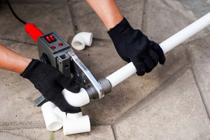
Why the gauge falls when nothing is leaking
Three causes account for most of it, and only one of them is a leak.
Temperature. Water contracts as it cools. A system filled with mains water at 8 °C sitting in a building at 22 °C will move in the other direction — the water warms, expands, and the gauge climbs, then settles. Either way, a 10 K mismatch is enough to produce a reading that has nothing to do with the pipework, which is why the protocol makes temperature equalisation a precondition rather than a nicety. If you have to test in an unheated shell in winter, record the ambient and the water temperature on the report alongside the pressures. It is the only way to defend a marginal result later.
Visco-elastic expansion. The reason the 30-minute pumped phase exists. If you cut it short at 15 minutes because the pressure looked stable, the remaining expansion happens during your observation window and reads as decay.
Trapped air. A compressed air pocket slowly redistributes and dissolves, and the gauge tracks it down. This one is diagnosable: bleed the system properly and repeat. If the second test behaves, it was air.
What is left after you have excluded those three is a leak, and on a PPR system it is very likely a joint. Cold welds — where the socket or spigot did not reach fusion temperature — are the classic culprit, and they frequently hold at low pressure and open up under test. That is the test doing its job.
Testing with air instead of water
A water test leaves the system full of stagnant water, and on a potable installation that is a hygiene problem with a clock on it. The ZVSHK guidance is direct about when to reach for compressed air or inert gas instead: when a long standstill between the leak test and commissioning is expected — particularly at average ambient temperatures above 25 °C, to exclude bacterial growth — or when the pipe cannot remain completely filled, for example because of a frost period.
If you do use water and cannot commission immediately, the constraint is explicit: a water exchange must be ensured at regular intervals, at the latest after seven days, from the time of the leak test until the installation is commissioned. Seven days is not a suggestion you can average out over a fortnight.
| Air test | Pressure | Duration | Notes |
|---|---|---|---|
| Leak test | 150 mbar | At least 120 minutes for up to 100 litres of pipeline volume; add 20 minutes for every further 100 litres | Manometer indication precision of 1 mbar required |
| Strength (load) test — smaller sizes | Max 3 bar | 10 minutes | Nominal widths up to 63 × 4.5 mm (up to DN 50) |
| Strength (load) test — larger sizes | Max 1 bar | 10 minutes | Nominal widths above 63 × 4.5 mm (DN 50 to DN 100) |
The pressure ceiling drops as diameter rises for a straightforward safety reason: stored energy in compressed gas scales with volume, and a large-bore plastic line failing at 3 bar of air is genuinely dangerous in a way that the same line failing under water is not. Water is incompressible, so a hydrostatic failure is a spray. A pneumatic failure is a projectile. Clear the area, and never improvise upward from these figures because “it’s only 3 bar.”
A worked example, end to end
Take a six-storey residential block. Cold and hot risers in PN20 PPR, boosted supply, maximum working pressure at the base of the riser 5 bar. The specification names BS EN 806-4 and asks for a documented test before the shafts are boarded. Here is how the numbers fall out.
- Establish MDP. Maximum working pressure is 5 bar. The statutory reference point is 1.5 × 5 = 7.5 bar. Test pressure under EN 806-4 is 1.1 × 7.5 = 8.25 bar. Note that the PN20 rating never entered the calculation — it only tells you the pipe can take it.
- Isolate. Booster set out, expansion vessels out, cylinder disconnected, every branch capped in metal. Test the riser as a riser, not as part of a plant room.
- Fill and settle. Filtered water, bleed from the top floor down, then 30 minutes to equalise because the shaft is 6 °C colder than the mains water. Record both temperatures.
- Pre-test. 15 minutes at supply pressure. Walk the shafts with a torch. Two threaded transitions weeping — fix them now, at 4 bar, not later at 8.25.
- Pump to 8.25 bar and hold by pumping for 30 minutes. You will be topping up noticeably for the first ten. That is the polypropylene expanding, and it is expected.
- Stop pumping. Read at 30 minutes. Allowance is 0.6 bar, so anything at or above 7.65 bar continues. Say it reads 7.9 bar — a 0.35 bar drop, comfortably inside.
- Hold a further 120 minutes. Allowance from the 30-minute reading is a further 0.2 bar, so the floor is 7.7 bar. Final reading 7.82 bar. Pass, with no visible leakage.
- Document immediately. Test pressure, both intermediate readings, both temperatures, gauge serial and resolution, date, time, the procedure used, and who witnessed it.
Total elapsed time from first pump stroke: three hours. Add filling, bleeding and equalisation and you should block out most of a working day per riser section. Contractors who budget forty minutes for this are budgeting for Test A on a bungalow.
Test record — the fields that matter at handover
Project and section tested · procedure applied (EN 806-4 Test A / Test B, or ZVSHK plastic-pipe method) · maximum design pressure · calculated test pressure · pressure at each stage boundary with times · ambient and water temperature at fill and at final reading · gauge make, serial and resolution · confirmation that apparatus and vessels were isolated · confirmation of metal end closures · result and signatures. Keep it on one page. A test record nobody can read is a test record nobody will accept.
Acceptance record template, filled from the example above
The box above lists the fields. This is the same record laid out as the one-page form we ask contractors to attach when a warranty question comes up, with the six-storey riser filled in. Copy the left two columns onto your own sheet; the third column is only there to show what a complete entry looks like.
| Record field | What to enter (unit) | Example: 5 bar cold riser, PN20 PPR |
|---|---|---|
| Section tested | Riser / floors / drawing reference | Cold riser R1, ground to fifth floor |
| Procedure | EN 806-4:2010 Test A / Test B / ZVSHK | Test B |
| Maximum design pressure | bar, with its basis | 7.5 (1.5 × 5 bar maximum working pressure) |
| Test pressure | 1.1 × MDP (bar) | 8.25 |
| Temperatures at fill | Pipe / water (°C); equalisation time (min) | Shaft 6 K colder than mains; 30 min wait |
| End of pumped hold | Reading at 30 min (bar), time | 8.25 held by pumping |
| First observation | Reading 30 min after pump off (bar); allowance 0.6 | 7.90 (drop 0.35) |
| Second observation | Reading after a further 120 min (bar); allowance 0.2 | 7.82 (drop 0.08) |
| Gauge | Make, serial, resolution (bar), position | 0.1 bar resolution, lowest point of riser |
| Isolations | Vessels, heaters, booster out; metal end caps | Confirmed, all branches capped in brass |
| Result and signatures | Pass / fail; installer, witness; date, time | Pass, no visible leakage; two signatures |
| Source: field list per BS EN 806-4:2010 clause 6.1.3 and the Water Regulations Guide; allowances per Test B. Add a flushing line (EN 806-4 clause 6.2: ≥ 2 m/s, water exchanged at least 20 times) if commissioning follows the same day. | ||
The two temperature entries are the ones most often missing from a disputed PPR record, and without them a 0.3 bar drop on a winter site cannot be separated from a weeping joint. For PPR going into a chase, the test must be complete before the plaster goes on; the sequence is in chasing and in-wall PPR.
After the pass: flushing, standstill and commissioning
A passed pressure test proves the system is tight. It says nothing about whether the water coming out of it is fit to drink, and the two get conflated constantly.
EN 806-4 sets the flushing requirement: a minimum flow velocity of 2 m/s, with the water in the system replaced at least 20 times. Flushing starts on the lowest floor and works upwards, line by line, with the flushing water filtered to retain particles of 150 micrometres or larger. The 2 m/s figure is the load-bearing one — below that velocity you are rinsing, not flushing, and debris from cutting and fusion stays where it settled.
Then the seven-day clock. If the system stays water-filled between test and commissioning, water exchange has to happen at regular intervals, at the latest after seven days. On a project running months behind on second fix, that is a real operational commitment that somebody has to own in writing — otherwise you hand over a system that passed every mechanical test and still fails a microbiological sample.
The site test is not the factory test
Your pressure test proves the assembly — the joints you made, the caps you fitted, the valves you installed. It cannot tell you anything about the long-term pressure capability of the pipe itself, because that is established over thousands of hours in a lab, not over three hours on a landing.
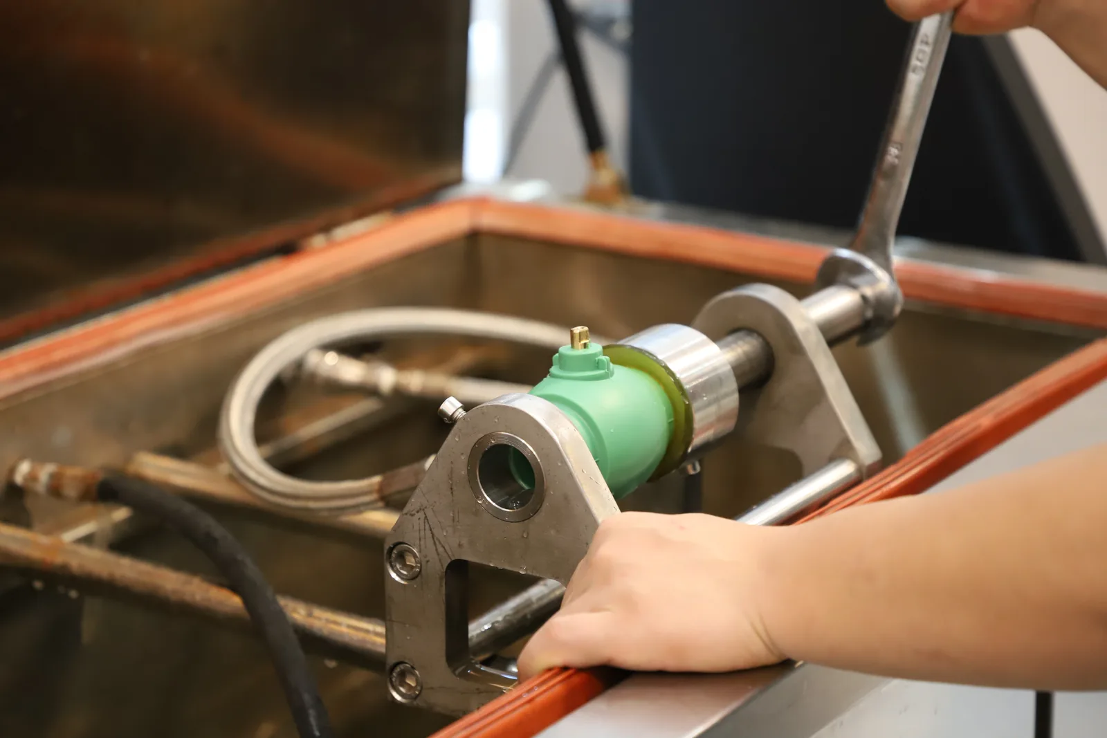
Under ISO 15874-2:2013 (current edition, with amendments A1:2018 and A2:2022), PP-R pipe is qualified against internal-pressure requirements tested to ISO 1167-1 and ISO 1167-2, on three test pieces per condition, with no failure permitted during the test period:
| Hoop stress | Temperature | Test period |
|---|---|---|
| 16.0 MPa | 20 °C | 1 hour |
| 4.3 MPa | 95 °C | 22 hours |
| 3.8 MPa | 95 °C | 165 hours |
| 3.5 MPa | 95 °C | 1000 hours |
Those four rows are what separates PP-R from cheaper polypropylene grades. PP-B holds 16.0 / 3.5 / 3.0 / 2.6 MPa across the same conditions and PP-H holds 21.0 / 5.1 / 4.2 / 3.6 — so at 95 °C for 1000 hours, PP-R sits above PP-B by a margin that matters on a hot-water riser.
Behind the table sits the longer chain. Pipe material is evaluated to ISO 9080 using internal-pressure tests per ISO 15874-2 to derive σ-LPL values, with samples tested at 20 °C, 60–70 °C and 95 °C and at least three failure times in each of the intervals 10–100 h, 100–1000 h, 1000–8760 h and above 8760 h. At least 97.5 % of results must lie on or above the reference line. That evidence chain — not a marketing line — is what supports a 50-year design life at rated pressure and 20 °C under ISO 15874.
Bekaatherm’s PPR systems are built and certified against that framework — ISO 15874-1 (general), -2 (pipes), -3 (fittings) and -5 (fitness for purpose of the assembled system), with dimensions to DIN 8077:2008-09 and general quality requirements to DIN 8078:2008-09, and third-party certification from SKZ in Germany, CE, and WRAS. The batch-level side of that — what actually gets checked before pipe ships — is set out on our quality control process page, and the certificate scans themselves are on the certifications page.
How the test relates to your warranty
Bekaatherm carries a 50-year warranty against material and manufacturing defects, matched to the 50-year design life the ISO 15874 framework establishes. Two words in that sentence do a lot of work: material and manufacturing. A material or manufacturing defect is ours. A cold weld, an over-inserted fusion joint, a system operated above its design pressure, or a plastic test cap that crept at 8 bar are installation matters, and no manufacturer’s warranty in this industry covers them.
Which is precisely why the test record matters commercially, not just technically. A documented EN 806-4 pass, with the procedure named and the readings recorded, is the cleanest available evidence that the installation was sound at handover. Without it, any later failure becomes an argument between the installer and the supplier with no facts in the middle. Contractors who keep a one-page record per section resolve those conversations in a morning. Contractors who do not, do not.
A note on scope, because requirements vary: national and local rules differ on which test procedure is mandatory, who may witness it, and what has to be retained. EN 806-4 is the European reference and BS EN 806-4:2010 is the current edition in the UK, but some national codes use a different multiplier with a fixed pressure floor instead. Confirm the applicable procedure with your building control body or the relevant water authority before you commit a method statement.
Choosing pipe you can actually defend after a failed test
When a test fails on site, the first question anyone asks is whether the pipe was any good. Answering it takes documents, not opinions — and the time to collect them is at the purchase order, not after the screed is down.
Three things are worth insisting on. A mill certificate that names the ISO 15874-2 conditions actually tested, not a generic “conforms to ISO” line. Pipe marked with the standard and the PN class along its length, so a section cut out of a wall is still identifiable. And a supplier who will tell you which of their sizes are regular in-production items — at Bekaatherm those ship in 15–25 days, and the 98 items across the four systems are held as a matched range so pipe, fittings and valves come from one certification envelope rather than three.
If you are still deciding between classes, the practical trade-off between PN20 and PN25 for hot-water risers is worth reading before you specify: our comparison of PN20 vs PN25 pressure ratings covers where the extra wall thickness earns its cost and where it does not.
Specifying PPR for a project where the test report is a contractual deliverable?
For contractors and consulting engineers who need certification documents attached to the material submittal — mill certificates against ISO 15874-2, SKZ, CE and WRAS scope, and the batch test regime behind them. Tell us the project, the sizes and the market, and we will send the document pack that matches. Standard samples are free for up to three items, freight collect, if you want pipe in hand before you specify.
Request the certification pack
Ask a technical question on WhatsApp
Frequently asked questions
What pressure should PPR pipe be tested at?
Under EN 806-4, the test pressure is 1.1 × the maximum design pressure of the installation, applied by pumping — not 1.5 × the pipe’s PN rating. For a system with 5 bar maximum working pressure, that works out to 1.1 × (1.5 × 5) = 8.25 bar. The PN class tells you the pipe can withstand the test; it does not set the test figure.
How long does a PPR pressure test take?
EN 806-4 Test A takes 120 minutes: 30 minutes maintained by pumping, then 90 minutes at one third of test pressure. Test B takes 180 minutes: 30 minutes pumped, then 30 minutes plus a further 120 minutes of observation. The German ZVSHK plastic-pipe water method takes 150 minutes. None of these include filling, bleeding or temperature equalisation.
How much pressure drop is acceptable during the test?
Under EN 806-4 Test B, the pressure may not fall more than 0.6 bar over the 30 minutes after pumping stops, then not more than a further 0.2 bar over the following 120 minutes, with no visible sign of leakage. Under Test A, the pressure must not drop further over the 90-minute period after it has been reduced to one third of test pressure.
Why does my PPR pressure test keep failing when I cannot find a leak?
Three non-leak causes dominate. A temperature difference greater than 10 K between the installation and the test water, which requires a waiting period of about 30 minutes after filling. Visco-elastic expansion of the polypropylene, which is why the 30-minute pumped phase cannot be shortened. And trapped air, which behaves like a slow leak on the gauge. Also check your gauge resolves 0.1 bar and is fitted at the lowest point of the system.
Can I pressure test PPR with compressed air?
Yes, and it is preferred when a long standstill between the leak test and commissioning is expected — particularly at average ambient temperatures above 25 °C, to exclude bacterial growth — or when the pipe cannot stay completely filled, for instance during a frost period. The leak test runs at 150 mbar for at least 120 minutes for up to 100 litres of pipeline volume, with 20 minutes added per further 100 litres. The strength test is capped at 3 bar for sizes up to 63 × 4.5 mm and 1 bar above that, for 10 minutes.
Does an EN 806 pressure test satisfy UK water regulations?
Generally yes. The Water Fittings Regulations and Scottish Water Byelaws (Schedule 2, Paragraph 5) call for a test of at least 1.5 × maximum working pressure, while EN 806 gives 1.1 × that figure — 8.25 bar against a 7.5 bar statutory minimum on a 5 bar system. Because EN 806 recommends the slightly higher pressure, an installation satisfying EN 806 complies by default. Confirm the current requirement with your water undertaker for the specific project.
What do I do after the pressure test passes?
Flush before commissioning. EN 806-4 calls for a minimum flow velocity of 2 m/s with the water in the system replaced at least 20 times, starting on the lowest floor and working upwards line by line, with flushing water filtered to retain particles of 150 micrometres or larger. If the system then stands water-filled, water exchange must be ensured at regular intervals and at the latest after seven days until commissioning.
Is the site pressure test the same as the manufacturer’s test?
No. The site test proves the assembled installation is tight over a few hours. The factory qualification under ISO 15874-2:2013 tests the pipe material to ISO 1167-1 and ISO 1167-2 at 16.0 MPa hoop stress for 1 hour at 20 °C and at 4.3, 3.8 and 3.5 MPa at 95 °C for 22, 165 and 1000 hours respectively, on three test pieces per condition. A mill certificate proves the pipe; your test proves the joints.
Sourcing PPR for a project that has to pass an EN 806-4 test
This one is for importers and project buyers, not for anyone comparing single coils. Bekaatherm manufactures 98 items across four matched systems in a 120,000 m² plant in Türkiye and ships to 118+ countries; a mixed trial order is one 20GP container of pipe, fittings and valves, on 30% T/T deposit with the balance against copy B/L. Regular in-production sizes ship in 15–25 days.